Defect inspection apparatus and defect inspection method

Inactive Publication Date: 2007-09-13
ORMON CORPORATION
View PDF3 Cites 16 Cited by
  • Summary
  • Abstract
  • Description
  • Claims
  • Application Information

AI Technical Summary

Benefits of technology

[0038]“A predetermined area” means that the first and second light sources are not point light sources but ranges of a certain size for irradiating light. “With a certain degree of incident angle” includes a case that a diffuse light is emitted from an arbitrary place within the predetermined area and a case that a divergent light and a convergent light are emitted. It means the light having a spread in an irradiation angle. In addition, it includes the light that spreads after collecting the light once, excluding a parallel light. Thus, it is possible to expand the area on the surface capable of receiving the regular reflection light of the inspection object, namely the area that can be inspected. This is effective for expanding the inspection area even when the inspection object is the curved surface.
[0039]An area having a predetermined size means the opening area having a limited size. When the imaging element itself has the limited size, the size of the opening area becomes limited. Also, by imaging through a light receiving lens, the size of the opening area becomes limited. With the structure described above, the spread of the irradiation light or propagation of the irradiation light on the edge part of the opening area is shield, and therefore light sensitivity of the peripheral part of the first and second regular reflection areas is sometimes deteriorated compared to the center part. Whether the defect is present or not is determined for the peripheral part having low light receiving sensitivity, so that the first regular reflection area and the second regular reflection area are superposed one another and the first and second inspection images are superposed one another. Thus, a stable defect inspection is possible even in the area with low sensitivity.
[0047]“A predetermined area” means that the first and second light sources are not point light sources but ranges of a certain size for irradiating light. “With a certain degree of incident angle” includes a case that a diffuse light is emitted from an arbitrary place within the predetermined area and a case that a divergent light and a convergent light are emitted. It means the light having a spread in an irradiation angle. In addition, it includes the light that spreads after collecting the light once, excluding a parallel light. Thus, it is possible to expand the area on the surface capable of receiving the regular reflection light of the inspection object, namely the area that can be inspected. This is effective for expanding the inspection area even when the inspection object is the curved surface.
[0048]An area having a predetermined size means the opening area having a limited size. When the imaging element itself has the limited size, the size of the opening area becomes limited. Also, by imaging through a light receiving lens, the size of the opening area becomes limited. With the structure described above, the spread of the irradiation light or propagation of the irradiation light on the edge part of the opening area is shield, and therefore light sensitivity of the peripheral part of the first and second regular reflection areas is sometimes deteriorated compared to the center part. Whether the defect is present or not is determined for the peripheral part having low light receiving sensitivity, so that the first regular reflection area and the second regular reflection area are superposed one another and the first and second inspection images are superposed one another. Thus, a stable defect inspection is possible even in the area with low sensitivity.

Problems solved by technology

However, along with a diversification and a mass-production of a product using this type of case, a load of a worker is increased, and time required for the inspection is also enormous.
Namely, when the inspected surface is the curved surface, a problem involved therein is that a detection accuracy of the defect is deteriorated when the light source is made large to widen the inspection area.
This is because a size of the lens and the size of the light source of the imaging apparatus are limited.
However, actually, the pixel PX2 can only partially receive the light emitted from the light source 101.

Method used


Image

  • Defect inspection apparatus and defect inspection method
  • Defect inspection apparatus and defect inspection method
  • Defect inspection apparatus and defect inspection method

Examples


embodiment 1

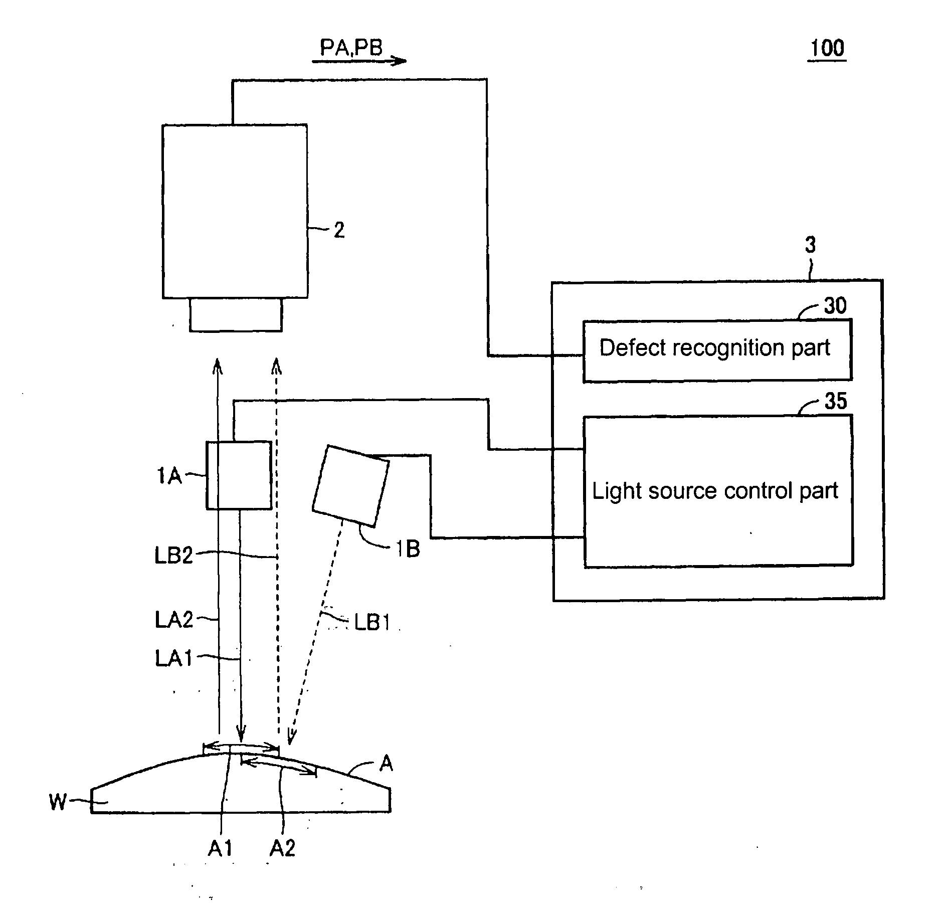
[0072]FIG. 1 shows a view showing a basic structure of a defect inspection apparatus of an embodiment 1.

[0073]In FIG. 1, a defect inspection apparatus 100 inspects whether a defect is present on a glossy surface of a work W (inspection object). Note that the defect means an irregularity defect (defect in an appearance of a convex shape or a concave shape compared to a periphery).

[0074]The work W is a metal or a resin coated with a transparent material on its surface. Note that in FIG. 1, the surface of the work W (inspected surface A) is a curved surface. However, the surface of the work W may be a flat surface.

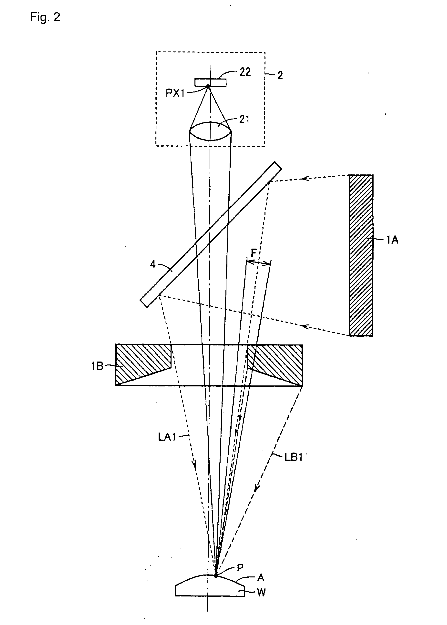
[0075]The defect inspection apparatus 100 includes a plurality of light sources 1A, 1B, an imaging apparatus 2, and a main control part 3.

[0076]The light source 1A emits irradiation light LA1 toward the inspected surface A. Therefore, an irradiation area A1 is formed on the inspected surface A. The irradiation light LA1 is regularly reflected on the inspected surface A. Thus,...

embodiment 2

[0123]An entire body of the defect inspection apparatus of the embodiment 2 is the same as the structure of the defect inspection apparatus 100 as shown in FIG. 1. Therefore, the explanation thereafter is not repeated for the structure of the defect inspection apparatus of the embodiment 2. In addition, the block diagram of the main control part provided in the defect inspection apparatus of the embodiment 2 is the same as the block diagram as shown in FIG. 3. Therefore, the explanation thereafter is not repeated.

[0124]The defect inspection apparatus of the embodiment 2 is different from the embodiment 1, in the point of having the same peak wavelengths of the irradiation lights LA1 and LB1 in FIG. 1 (namely, having the same the characteristics). In addition, the main control part 3 turns on the light sources 1A and 1B sequentially. In these points, the defect inspection apparatus of the embodiment 2 is different from the defect inspection apparatus of the embodiment 1.

[0125]When th...


PUM


Abstract

Light sources emit irradiation lights respectively, so that edge parts of mutual irradiation areas (inspection areas) are superposed one another. The imaging apparatus receives regular reflection lights and generates two images corresponding to each of the light sources. A main control part combines two images and determines presence / absence of a defect. By irradiating an inspected surface A with the irradiation lights from mutually different directions, a position of an area showing the defect in each image is slightly deviated. Therefore, even if a dimension of an area showing the defect is small in each image, by superposing two images one another, the dimension of the area showing a defect part becomes large in the image after composition. Thus, an accuracy of defect detection on the edge part of the inspection area can be improved.

Description

BACKGROUND OF THE INVENTION[0001]1. Field of the Invention[0002]The present invention relates to a technique of inspecting whether or not a defect is produced on a surface of a work, and particularly relates to a technique of inspecting in the vicinity of an edge part of an inspection area.[0003]2. Description of the Related Art[0004]In recent years, a case of a cellular phone and a home electric appliance, etc, having a structure that a coating layer is formed by a transparent resin on the surface of a main body, has been used. In such a case, the main body part is generally formed by resin, etc, and is colored in a predetermined color. By forming the aforementioned coating layer on the surface of this main body part, gloss and a change of color are generated on the surface, and a commodity value is thereby improved.[0005]In a plant where a molding body having the aforementioned coating layer is manufactured, whether or not irregularity is generated on the surface of the coating la...

Claims


Application Information

Patent Timeline
IPC IPC(8): G01N21/88
CPCG01N21/8806G06T1/00G01B11/30G01N21/88
Inventor OKABE, HIROSHIKANETANI, YOSHIHIROMATSUMOTO, TOSHIHIKO
Owner ORMON CORPORATION
Why Eureka
Try Eureka