
Three-dimensional shape measurement apparatus and method for eliminating2pi ambiguity of moire principle and omitting phase shifting means

Inactive Publication Date: 2007-09-13
KOREA ADVANCED INST OF SCI & TECH
View PDF3 Cites 42 Cited by
  • Summary
  • Abstract
  • Description
  • Claims
  • Application Information

AI Technical Summary

Benefits of technology

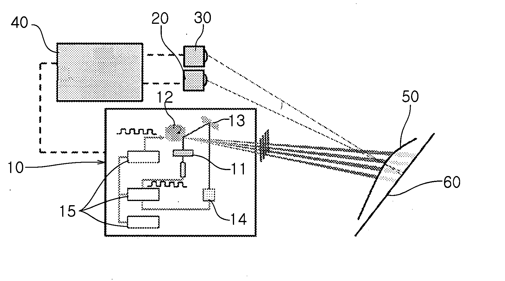
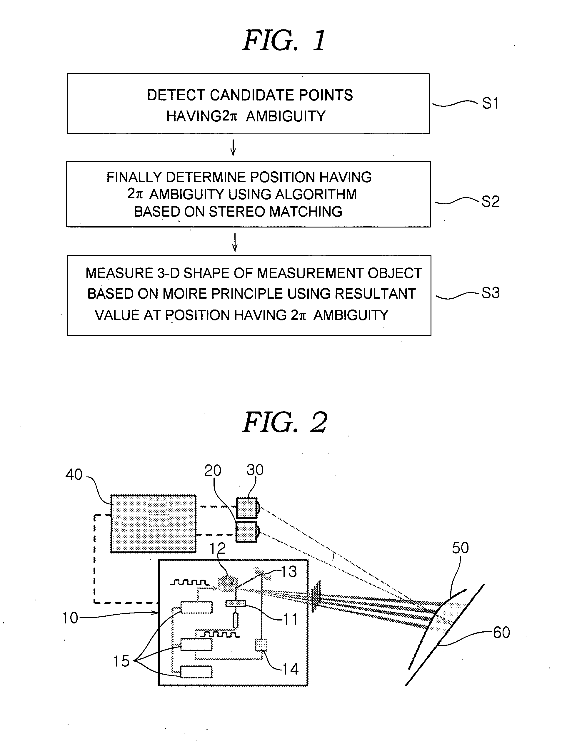
[0006]Accordingly, the present invention has been made under consideration of the above problems in the prior art. The first objective of the present invention is to provide a 3-D shape measurement apparatus and method that can more precisely measure a 3-D shape, eliminating 2π ambiguity while adopting the typical Moire principle. The second objective of the present invention is to provide a 3-D shape measurement apparatus and method that can detect the depth value of an object by using only one stereo image without requiring a hardware means for shifting the phase of the projected fringe pattern, unlike the prior art.

Problems solved by technology

However, it has an inherent limitation: 2π ambiguity, which occurs when target objects have a depth greater than the pitch of a projected fringe pattern.
However, the conventional 3-D shape measurement method using the Moire principle still has a problem in that, if two measurement objects are spaced apart from each other by a distance of 2π or more, it is difficult to determine whether the resultant value of measurement is caused by the 2π ambiguity or that it indicates a measurement object having a depth of more than 2π.
Consequently, incorrect measurement results may occur.
Therefore, in the prior art, much effort was devoted to solving 2π ambiguity using other methods.
However, this technology is problematic in that, even if the 3-D shape information about the object can be relatively precisely measured while eliminating 2π ambiguity, hardware, such as an actuator for shifting the phase of the fringe pattern, must be provided.
In addition, considerable time is required to measure the 3D shape of the object.

Method used


Image

  • Three-dimensional shape measurement apparatus and method for eliminating2pi ambiguity of moire principle and omitting phase shifting means
  • Three-dimensional shape measurement apparatus and method for eliminating2pi ambiguity of moire principle and omitting phase shifting means
  • Three-dimensional shape measurement apparatus and method for eliminating2pi ambiguity of moire principle and omitting phase shifting means

Examples


experiment 1

[0035] Measurement object 51 having a thickness of 50 mm, as shown in FIG. 6A, was measured using the experimental apparatus of FIG. 5. The pattern images detected by the first and second cameras 20 and 30 are as shown in FIG. 6C. In this case, the conventional 3-D shape measurement method uses only the pattern projector 10 and the first camera 20 to measure object 51 based on the typical Moire principle, and thus derives the results shown in FIG. 6D. Further, the 3-D shape measurement method according to the present invention uses the pattern scanner 10 and the first and second cameras 20 and 30 to measure object 51 based on the typical Moire principle, and thus derives the results shown in FIG. 6E. That is, since the thickness (50 mm) of object 51 is less than the pitch of the fringe pattern, the conventional method and the method of the present invention derived the same experimental results, as shown in FIGS. 6D and 6E.

experiment 2

[0036] As shown in FIG. 7A, measurement object 52 having a thickness of 80 mm was spaced apart from the reference surface 60 by 90 mm, and was measured using the experimental apparatus of FIG. 5. The pattern images detected by the first and second cameras 20 and 30 are as shown in FIG. 7C. In this case, the conventional 3-D shape measurement method uses the pattern projector 10 and only the first camera 20 to measure object 52 based on the typical Moire principle, and thus derives the results shown in FIG. 7D. However, the 3-D shape measurement method of the present invention uses the pattern projector 10 and the first and second cameras 20 and 30 to measure object 52 based on the typical Moire principle, and thus derives the results shown in FIG. 7E. That is, in the conventional measurement method, since the distance between the front surface of object 52 and the reference plane is greater than 2π of the pattern period in the state in which object 52 is spaced apart from the refere...

experiment 3

[0037] As shown in FIG. 8A, a hemispherical measurement object 53 having a depth of 190 mm was measured using the experimental apparatus of FIG. 5. The pattern images detected by the first and second cameras20 and 30 are as shown in FIG. 8C. Here, the conventional 3-D shape measurement method uses the pattern projector 10 and only the first camera 20 to measure object 53 based on the typical Moire principle, and thus derives the results of FIG. 8D. The 3-D shape measurement method according to the present invention uses the pattern projector 10 and the first and second cameras 20 and 30 to measure object 53 based on the typical Moire principle, and thus derives the results of FIG. 8E. That is, it is impossible to secure accurate spatial information about object 53 using the conventional measurement method, but the measurement method of the present invention obtains 3-D shape information identical to the actual spatial information about object 53, as shown in FIG. 8E.

[0038]Therefore,...


PUM


Abstract

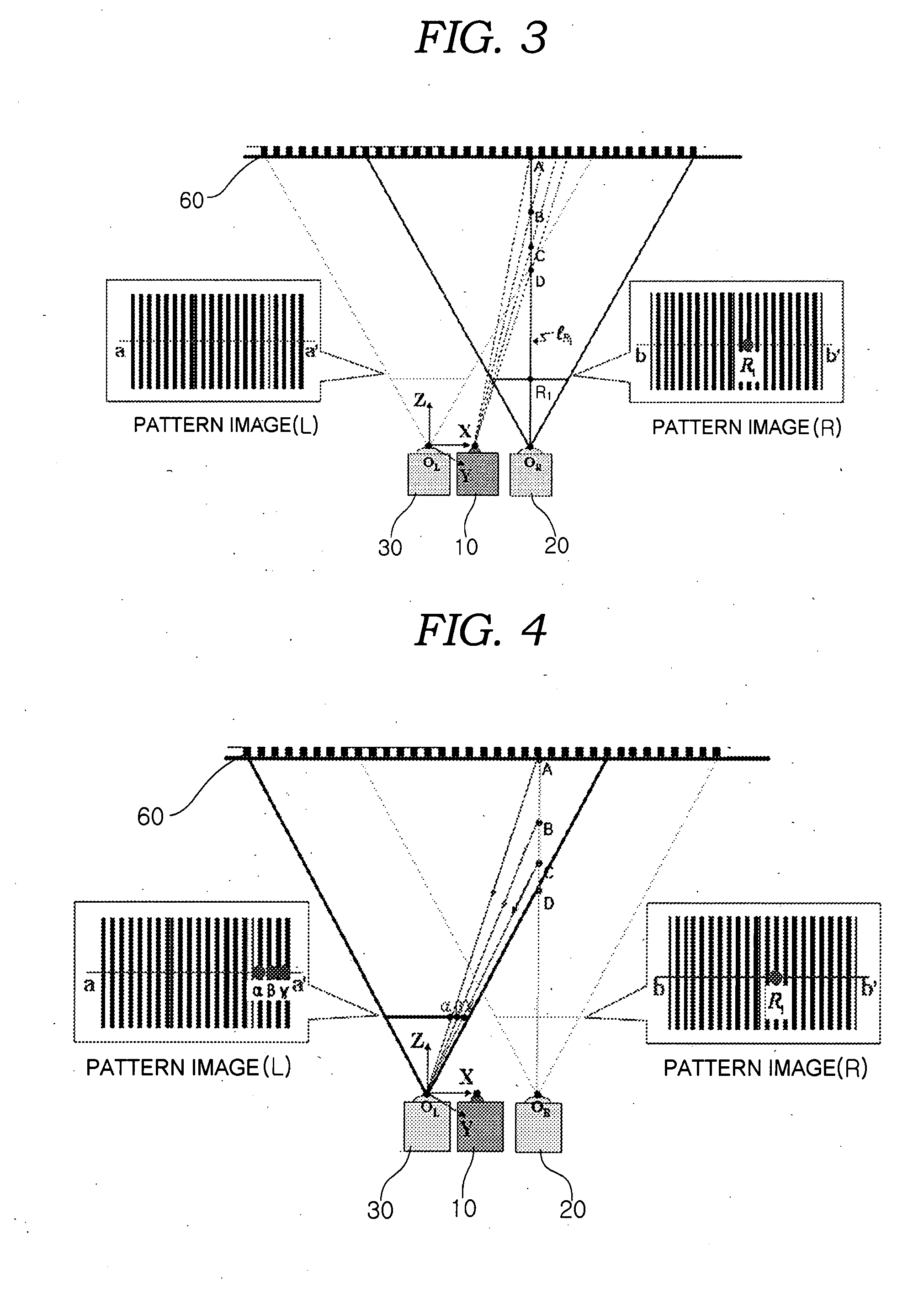
A three-dimensional (3-D) shape measurement method using a Moire measurement principle and a Stereo vision measurement principle is provided. The method comprises; a first step to detect candidate points and 3D positions of the candidate points in world coordinates which are identical results from typical Moiré technique by using a pattern projector, which adjusts a pitch of a fringe pattern and projects the fringe pattern to a measurement object, and a first camera, which detects a modulated fringe pattern caused by shape of shape of the object, by means of obtaining candidate points by comparing a reference fringe pattern to the modulated fringe pattern and calculating 3D positions at an arbitrary point on an image captured from the first camera; a second step to determine a final matching point among the candidate points detected from the first step by using the Stereo vision technique with the first and the second cameras, by means of projecting the 3D positions of the candidate points to an image plane of the second camera based on a camera matrix of the second camera, comparing intensity value of a projected point in the image plane of the second camera to intensity value of given point in the image plane of the first camera, and judging whether the candidate point is matched with an arbitrary point by using the stereo vision criteria; and a third step to measure the depth value of the arbitrary point by using the resultant value of the final matching point, which was determined at the second step. Therefore, the error of 2π ambiguity of the typical Moire principle is eliminated, and thus 3-D shape information can be more rapidly and accurately measured.

Description

BACKGROUND OF THE INVENTION[0001]1. Field of the Invention[0002]The present invention relates, in general, to a three-dimensional shape measurement apparatus and method using the Moire principle and Stereo vision principle, and more particular, to a three-dimensional shape measurement apparatus and method, which is implemented in order to prevent the error of 2π ambiguity from occurring in a measurement method using the Moire principle, thus more precisely measurement of the shape of a measurement target.[0003]2. Description of the Related Art[0004]Several techniques including an optical triangulation method using a laser structured light, a stereo vision method using two intensity images, the Moire technique, etc. have been developed to measure the three-dimensional (3-D) shapes of objects. Among these methods, the Moire measurement method has widely been used because it offers excellent precision and short time for measuring timely measurement of 3D shape. However, it has an inher...

Claims


Application Information

Patent Timeline
IPC IPC(8): G01B11/24
CPCG01B11/25D06Q1/08
Inventor LEE, KICHO, HYUNG SUCK
Owner KOREA ADVANCED INST OF SCI & TECH
Learn More