Decimator And Decimating Method For Multi-Channel Audio

a decimator and multi-channel audio technology, applied in the field of decimators and decimating methods for digital signal processing, can solve the problems of large order requirements inability of the receiving side to perform coherent demodulation, and the need for large order quantities of actual fir filters, so as to reduce the manufacturing cost of hardware circuits and power consumption.

Inactive Publication Date: 2007-09-13
HIMAX TECH LTD
View PDF2 Cites 0 Cited by
  • Summary
  • Abstract
  • Description
  • Claims
  • Application Information

AI Technical Summary

Benefits of technology

[0016]An objective of the present invention is to provide a decimator and a decimating method to perform the digital signal processing of multi-channel audio, which is capable of reducing the manufacturing costs of hardware circuits as well as their power consumption. Additionally, the present invention may also be applied to other multi-channel digital signals, and is not limited to audio signals.

Problems solved by technology

Accordingly, the receiving side cannot perform coherent demodulation.
The actual FIR filter generally requires an extremely large order.
If the conventional register is used to act as a time delayer, the manufacturing cost of the hardware circuits including the four decimators (shown in FIG. 1(b)) is extremely high.
Meanwhile, since the registers are serially connected with each other, when the FIR filter is operated, the transition of the logic level of the register has high frequency, based on the generation of the circuit clocks, resulting in heavy power consumption.

Method used


Image

  • Decimator And Decimating Method For Multi-Channel Audio
  • Decimator And Decimating Method For Multi-Channel Audio
  • Decimator And Decimating Method For Multi-Channel Audio

Examples


first embodiment

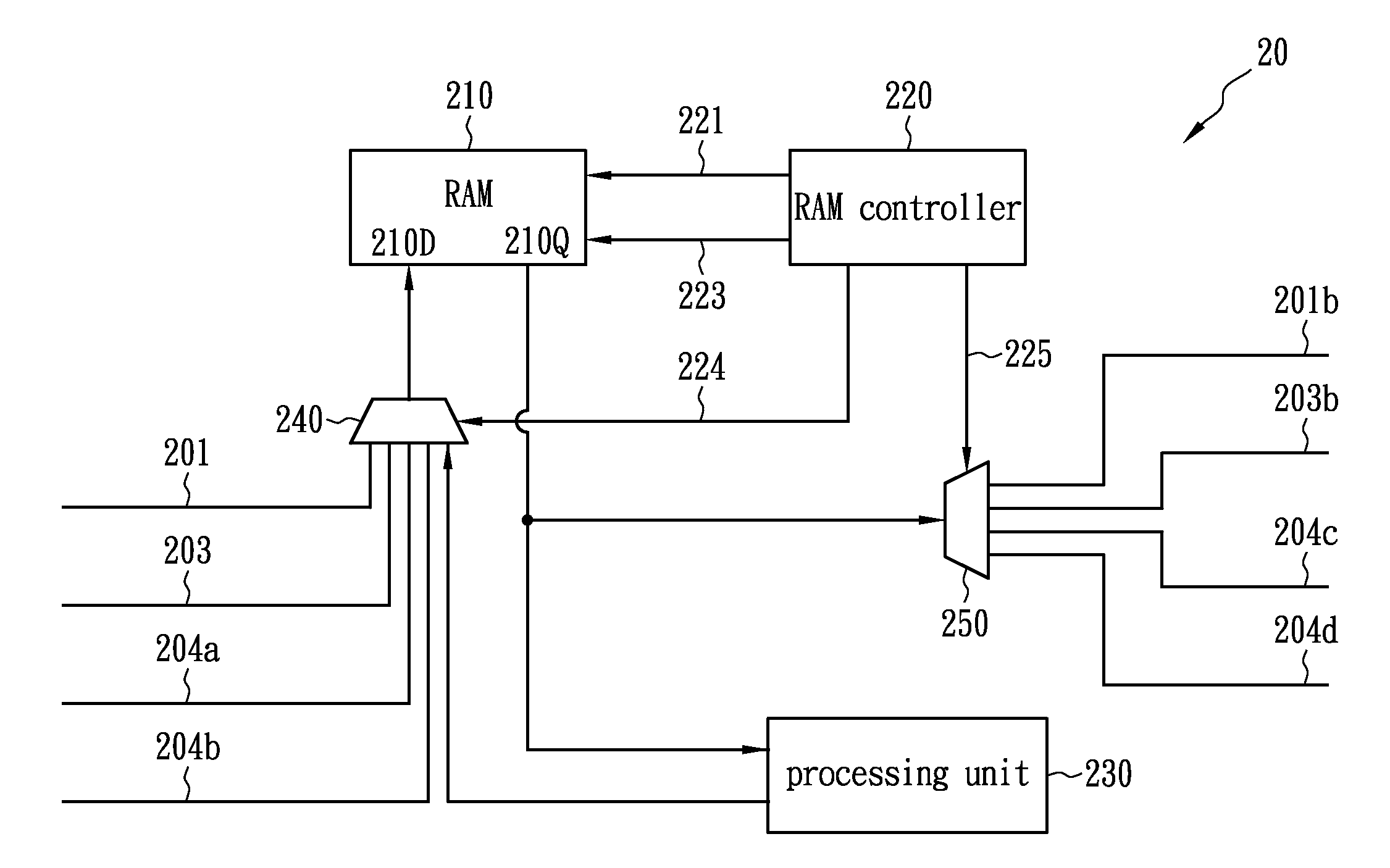
[0032]FIG. 2 is a schematic block diagram of a decimator 20 with a memory as a basic circuit according to the present invention. As to input signals of the decimator 20, in addition to a single-track signal 201 originally being the base band signal, a stereo difference signal 203, a second audio program in-phase (SAP_I) signal 204a and a second audio program quadrature phase (SAP_Q) signal 204b are signals with the base band signals as the main part in the spectrum after being mixed and decimated by a frequency mixer. However, there is still some portion of the high-frequency signals derived from the mixing and decimating process.

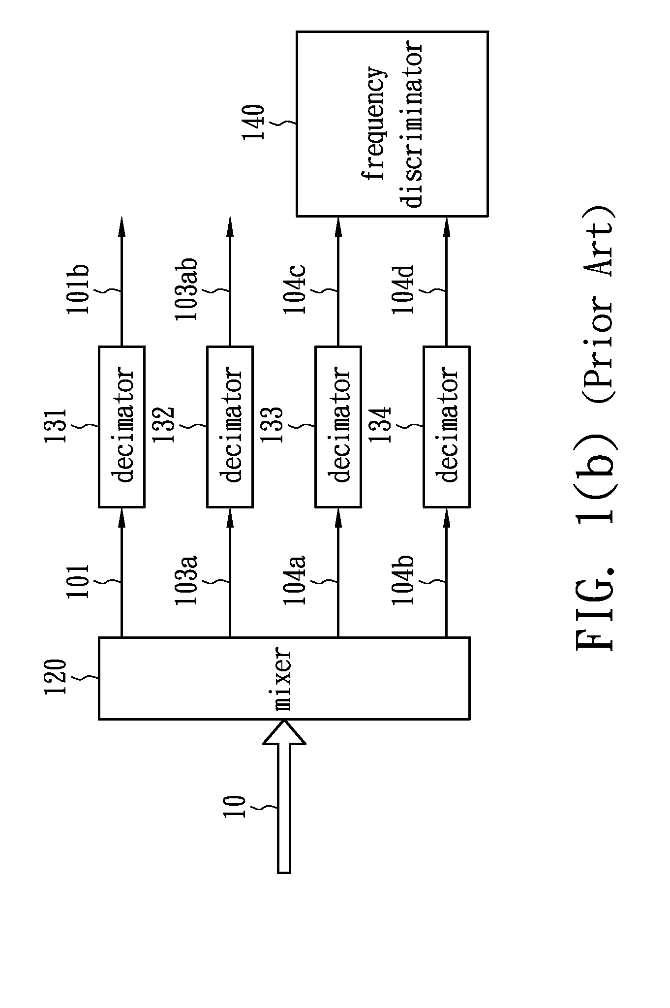
[0033]Unlike the conventional art, the four input signals in the present invention are digital signals processed for decimation by a single decimator 20, instead of being processed by four decimators, as shown in FIG. 1(b).

[0034]The decimator 20 comprises a RAM 210, a RAM controller 220, a processing unit 230, a multiplex 240 and a demultiplex 250.

[0035]The...

second embodiment

[0045]FIG. 3 is a schematic block diagram of a decimating system according to the present invention. The decimator 20 outputs the second audio program in-phase (SAP_I) signal 204c and the second audio program quadrature phase (SAP_Q) signal 204d to a frequency discriminator 350. The frequency discriminator 350 includes an FIR filter 351 and an FM demodulator 352, and the second audio program in-phase (SAP_I) signal 204c and the second audio program quadrature phase (SAP_Q) signal 204d are first low-pass filtered by the FIR filter 351 and sequentially FM demodulated by the FM demodulator 352. The time delayer of the FIR filter 351 in this embodiment may also be implemented as a memory cell of the RAM 210, thereby reducing the hardware space requirement.

[0046]FIG. 4 is a schematic block diagram of a decimating system according to a third embodiment of the present invention, which is different from the second embodiment in that there are only three input and output channels of the deci...


PUM


Abstract

A decimator is used to process a multi-channel audio signal, and includes a memory, a controller and a processing unit. The processing unit is used to decimate each input audio component of a multi-channel audio signal to generate corresponding multi-channel operational data. The controller is used to control read and write actions for each audio component of the multi-channel audio signal and the multi-channel operational data into or from the memory. The memory provides a digital signal process for decimation together with the processing unit. The input of the multi-channel audio and the output of the multi-channel operational data are performed through time division. Compared with conventional decimator circuits, the decimator circuit of the present invention reduces the cost and the power consumption of the hardware circuitry.

Description

BACKGROUND OF THE INVENTION[0001]1. Field of the Invention[0002]The present invention relates to a decimator and a decimating method for digital signal processing (DSP), and more particularly to a decimator and a decimating method for multi-channel audio processing.[0003]2. Description of the Related Art[0004]FIG. 1(a) is a spectrum distribution diagram of a television multi-track stereo (MTS) audio specified by the US broadcast television systems committee (BTSC). The television MTS audio 10 is a composite signal, which includes a single-track (L+R) signal 101, a pilot signal 102, a stereo difference (L−R) signal 103, a second audio program (SAP) signal 104 and a professional channel signal 105.[0005]The single-track (L+R) signal 101 is a base band signal, with a frequency of about 15 KHz. The frequency Fh of the pilot signal 102 is 15.734 KHz, which equals a horizontal scanning frequency of the BTSC video. The stereo difference (L−R) signal 103 is an amplitude modulation signal of...

Claims


Application Information

Patent Timeline
Patent Type & Authority Applications(United States)
IPC IPC(8): H04H5/00H04H1/00H04H20/34H04H40/45
CPCH04H40/45H04H20/34
Inventor TSAI, TIEN JUHUANG, CHAO WEI
Owner HIMAX TECH LTD
Why Eureka
Try Eureka