Method and System for Generating a Network Monitoring Display with Animated Utilization Information

a network monitoring and utilization information technology, applied in the field of methods and systems for monitoring data storage networks, can solve the problems of loss of revenues, decreased productivity, and increased complexity of data storage networks, and achieve the effect of providing redundant visual coding, high display motion speed, and high utilization ra

Inactive Publication Date: 2007-09-13
AVAGO TECH INT SALES PTE LTD
View PDF99 Cites 63 Cited by
  • Summary
  • Abstract
  • Description
  • Claims
  • Application Information

AI Technical Summary

Benefits of technology

[0012] The present invention addresses the above problems by providing a data traffic monitoring system that functions to determine performance of a data network, such as a data storage network, and to generate a performance monitoring display in a user interface. Significantly, the display includes a map or topology of the network with the performance shown with movement of displayed elements, such as line segments or dashes, to allow a network administrator to readily identify portions of the system that may be over utilized or underutilized as well as those that are being more properly utilized. In one embodiment, movement is used to show utilization of data connections between components of a data network, such as between servers and switches and the like, with the speed the displayed elements are shown to be moving corresponding or being proportional to the amount of utilization, i.e., with faster movement being used for higher utilizations. To show traffic flow in both directions, the display motion or movement includes two, parallel dashed lines that are shown moving in opposite directions to show performance, such as utilization, of a connection corresponding to a transmit and a receive channel of a connection.
[0014] Preferably, the system acts to periodically obtain updated or real-time performance information and in response, to periodically update the display such that the animation or rate of motion matches existing performance of the network. The display also typically includes a legend that includes motion and is colored as appropriate to show the user the meaning of the display. Further, if varying dash density or dash lengths are utilized, the legend would include similar lines with these dash densities or line segment lengths to indicate the corresponding parameter meaning, e.g., varying levels of data path utilization. In this manner, the system of the invention is able to not only show a topology of a monitored data network but to also effectively show performance information in the same display as the topology (i.e., on a single console or monitor screen), which simplifies monitoring efforts of network administrators.
[0016] The graphical representation may be a pair of dashed lines provided between communicatively linked components of the network. The generating then may include showing the dashes in the lines moving at a speed that is selected to represent the determined performance parameter, e.g., with higher display motion speeds used to shown higher utilization, and the dash or line segment motion is provided according to the invention so as to show the dashes in each line moving in a direction that matches data flow in the channel or connection being represented. Further, the line segment length (or dash length) represents the performance parameter with shorter lengths or dashes representing a higher performance parameter value. The generating may further involve displaying the graphical representation, such as lines, in one of a number of colors that are selected based on values or ranges of values of the performance parameter. Hence, the multiple settings or characteristics of the graphical representation can be used individually or in combination to provide an effective visual cue as to the value of the performance parameter and because of the position of the graphical representation the visual cue is quickly tied to the corresponding component of the network, whereby the graphical presentation effectively provides redundant visual coding.

Problems solved by technology

For a growing number of companies, planning and managing data storage is critical to their day-to-day business and any downtime or even delays can result in lost revenues and decreased productivity.
While managing a small network may be relatively straightforward, most networks are complex and include many components and data pathways from multiple vendors, and the complexity and the size of the data storage networks continue to increase when a company's need for data storage grows and additional components are added to the network.
Despite the significant improvements in data storage provided by data storage networks, performance can become degraded in a number of ways.
For example, performance may suffer when a network is deployed with few data paths to a storage device relative to the amount of data traffic.
Also, performance may be degraded when a data path includes devices, such as switches, connecting cable or fiber, and the like, that are mismatched in terms of throughput capabilities, as performance is reduced to that of the lowest performing device.
Further, even if the data paths and devices were originally planned to optimize the bandwidth of each critical data path and of device capabilities within the data paths, changes in usage patterns, such as archiving of data and deployment of new applications, and in network devices may significantly alter performance of the network.
Hence, an ongoing and challenging task facing network administrators is managing a network so as to avoid underutilization (i.e., wasted throughput capacity) and also to avoid overutilization (i.e., saturization of the capacity of a data path or network device).
The number and variety of devices that can be connected in a data storage network such as a SAN are often so large that it is very difficult for a network administrator to monitor and manage the network.
Understanding the physical layout or topology of the network is difficult enough, but network administrators are also responsible for managing for optimal performance and availability and proactively detecting and reacting to potential failures.
Unfortunately, existing network monitoring tools fail to meet all the needs of network administrators.
While the topology display or network map provides useful component and interconnection information, there is typically no useful information provided regarding the performance of the network.
For example, some monitoring tools display an icon as enlarged for components with higher utilization, which depending on the size of the network may be difficult to identify for an administrator monitoring tens to thousands of paths and components.
More typical monitoring tools only provide performance information in reports and charts that show utilization or other performance information for devices in the network at various times. These tools are not particularly useful for determining the present or real time usage of a network as an administrator is forced to sift through many lines and pages of a report or through numerous charts to identify problems and bottlenecks and often have to look at multiple reports or charts at the same time to find degradation of network performance.

Method used


Image

  • Method and System for Generating a Network Monitoring Display with Animated Utilization Information
  • Method and System for Generating a Network Monitoring Display with Animated Utilization Information
  • Method and System for Generating a Network Monitoring Display with Animated Utilization Information

Examples


Embodiment Construction

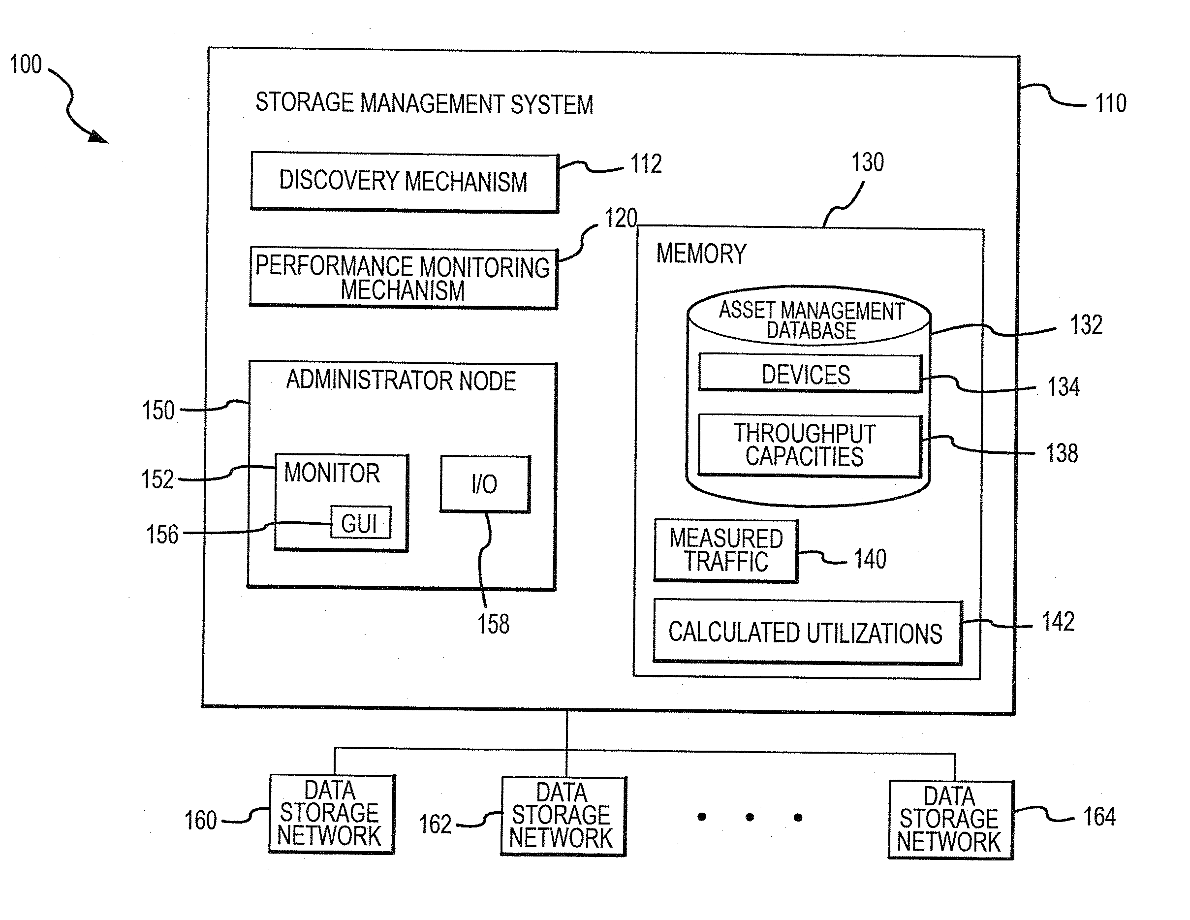
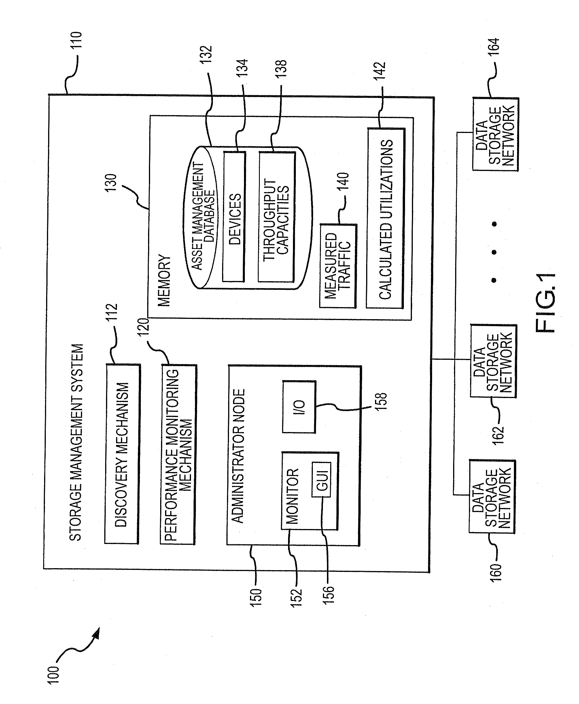
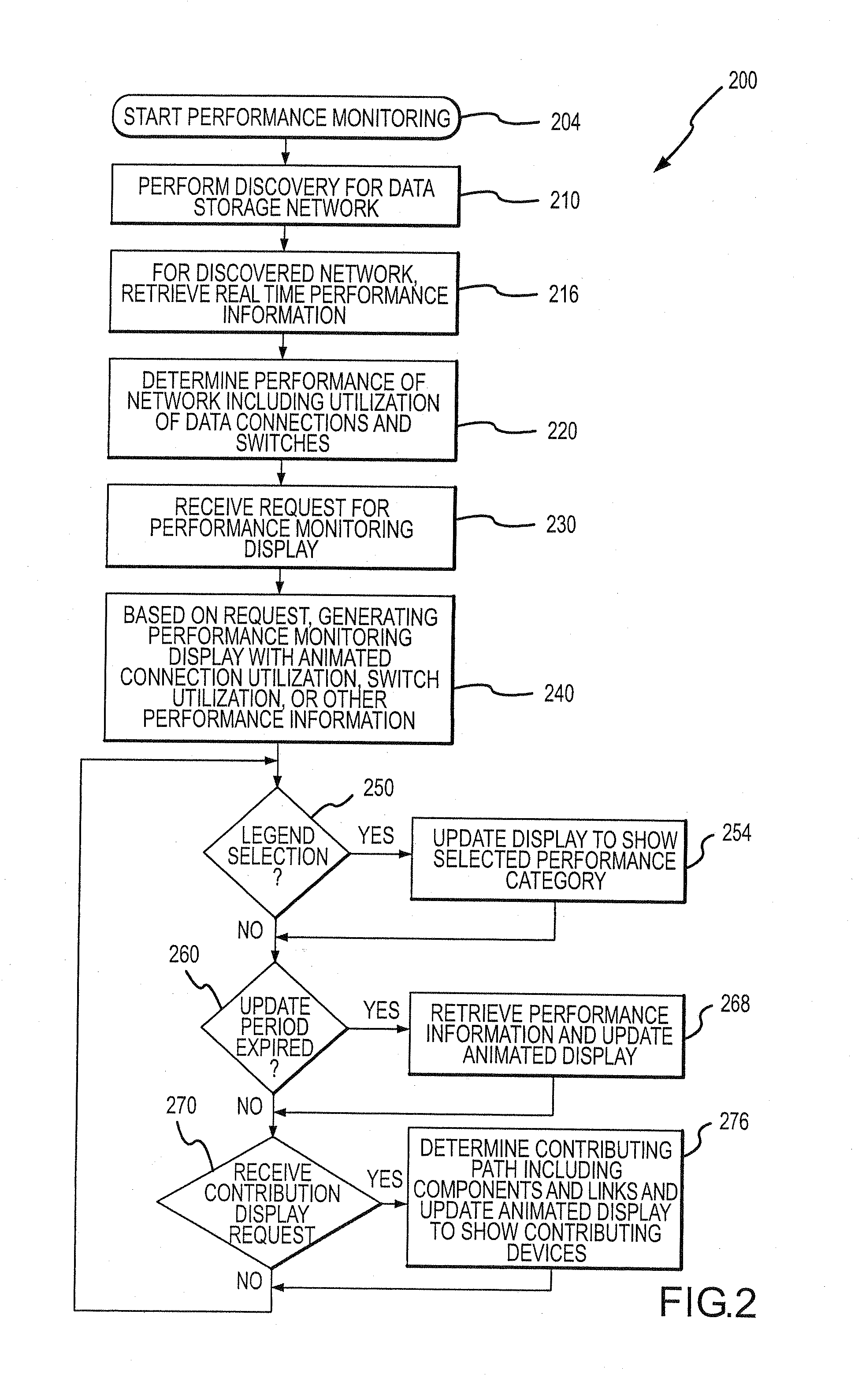
[0025] The present invention is directed to an improved method, and associated computer-based systems, for displaying performance information for a data network. The following description stresses the use of the invention for monitoring data storage networks, such as storage area networks (SANs) and network attached storage (NAS) systems, but is useful for monitoring operating performance of any data communication network in which data is transmitted digitally among networked components. An important feature of the method is that performance information, such as utilization of a data connection or link, is displayed in real time along with or as part of the topology of the network. For example, utilization of a data link is shown with the use of a dashed line for each data channel (i.e., transmit and receive), and in one embodiment, the length of the dashes or line segments is used to indicate various utilizations (i.e., the higher the utilization the smaller the dashes or line segm...


PUM


Abstract

A method for displaying storage network information in a user interface. The method includes identifying a topology map for a storage network and gathering operating information, which is processed to determine a performance parameter, such as utilization. A performance monitoring display is generated including a topology map and a graphical representation of the performance parameter, which is positioned in the display relative to the components for which the parameter applies. The graphical representation can be a pair of parallel dashed lines between communicating components. The dashes in the lines are moved using a speed coding scheme representative of the performance parameter, e.g., with faster speeds used to show higher ranges of utilization, and the direction of movement matches data flow. The dashed lines are colored using a color coding scheme and the line segment lengths vary in association with the performance value.

Description

CROSS REFERENCE TO RELATED APPLICATIONS [0001] The present application is a continuation of U.S. patent application Ser. No. 10 / 671,115 filed 24 Sep. 2003 entitled “Method and System for Generating a Network Monitoring Display with Animated Utilization Information,” which is hereby incorporated herein by reference in its entirety, which claims the benefit of priority pursuant to 35 U.S.C. § 119(e) of U.S. provisional application Nos. 60 / 415,001 and 60 / 415,002, both filed 30 Sep. 2002, which are incorporated by reference herein in their entireties.BACKGROUND [0002] 1. Technical Field [0003] The present invention relates generally to methods and systems for monitoring data storage networks, and more particularly, to a computer-based method and system for determining performance information for components and / or connections of a data storage network and for displaying in a user interface the performance information in an animated fashion that effectively shows a user on a single screen...

Claims


Application Information

Patent Timeline
Patent Type & Authority Applications(United States)
IPC IPC(8): G06F17/00H04L12/24H04L12/26
CPCH04L41/12H04L41/22G06F3/0484H04L43/16H04L43/026H04L43/0888H04L43/06G06F15/173H04L43/0882H04L43/045
Inventor ARQUIE, LOUIS M.HAMILTON, DAVID B.LUBECK, MARK R.
Owner AVAGO TECH INT SALES PTE LTD
Why Eureka
Try Eureka