
Method for manufacturing inkjet head, and inkjet head

Inactive Publication Date: 2007-09-20
SEIKO EPSON CORP
View PDF4 Cites 12 Cited by
  • Summary
  • Abstract
  • Description
  • Claims
  • Application Information

AI Technical Summary

Benefits of technology

[0013]In accordance with an advantage of some aspects of the invention, it is possible to provide an inkjet head and a method for manufacturing an inkjet head, whereby the yield in manufacturing non-defective head chips can be improved, their absolute quantity can be sufficiently secured, and thus the manufacturing cost can be lowered.

Problems solved by technology

When a desired number of nozzles is to be secured in a chip for inkjet head (hereafter also referred to as a head chip), which is an element for forming the inkjet head, the head chip becomes relatively large, compared to an IC chip, and therefore it is essentially difficult to improve the yield.
However, this manufacturing method has a problem in the accuracy in processing components other than pressure chambers, and therefore its ability in achieving higher integration is limited.
However, this manufacturing method requires additional steps of forming actuators and wirings to be connected to the actuators on a silicon substrate, compared to the method in related art in which pressure chambers alone are formed from a silicon substrate, such that the processing on the silicon substrate is prolonged, and defects that may be caused by foreign matters and deficiencies would likely occur.
As a result, the number of non-defective head chips that can be obtained from a single silicon substrate (silicon wafer) is not very high, in other words, a sufficient yield cannot be achieved.
Therefore, if defects occur in the pressure chambers due to, for example, foreign matters and deficiencies, the actuators and wirings that are normal, but formed on these defective pressure chambers, would consequentially become parts of defective products.

Method used


Image

  • Method for manufacturing inkjet head, and inkjet head
  • Method for manufacturing inkjet head, and inkjet head
  • Method for manufacturing inkjet head, and inkjet head

Examples


Embodiment Construction

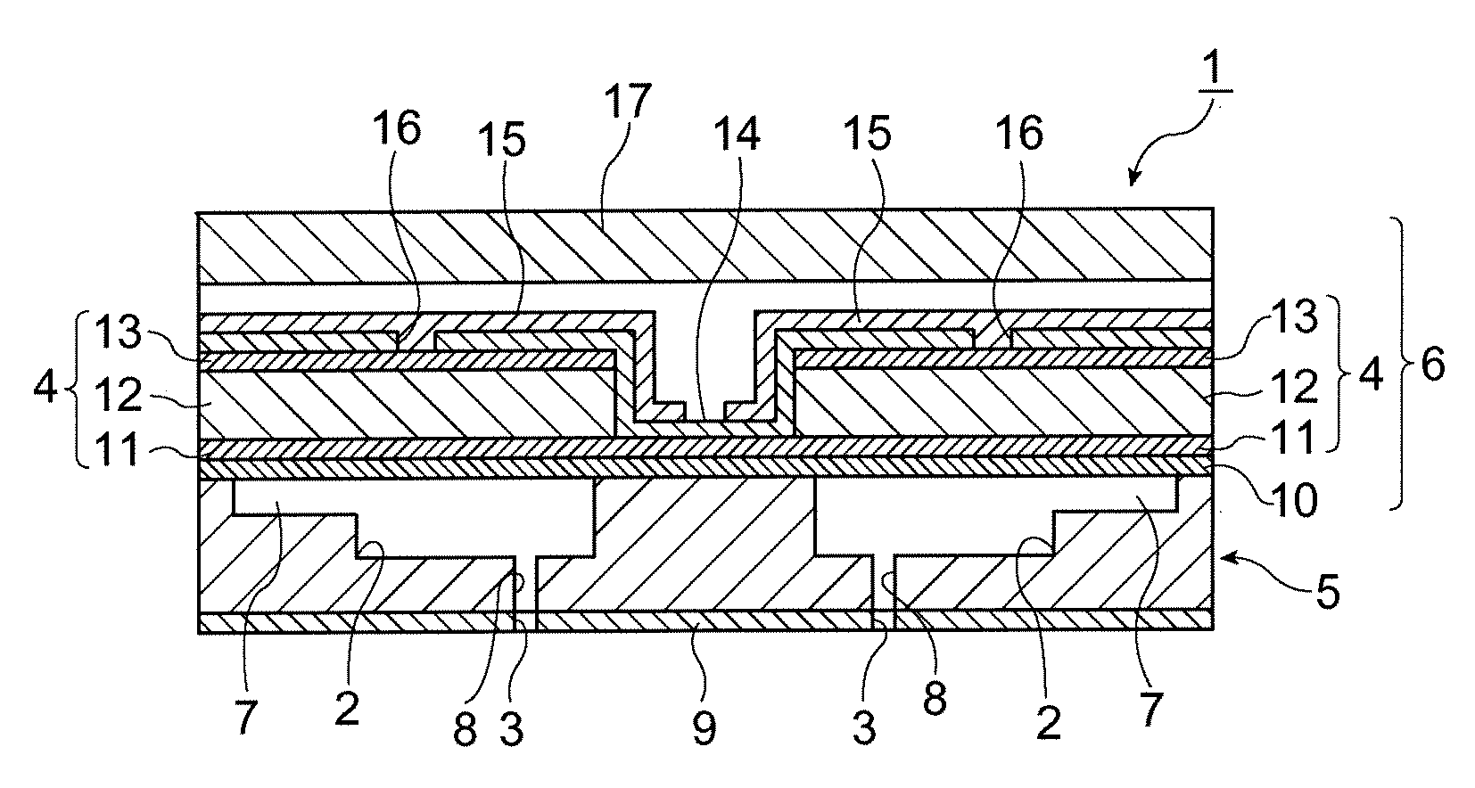
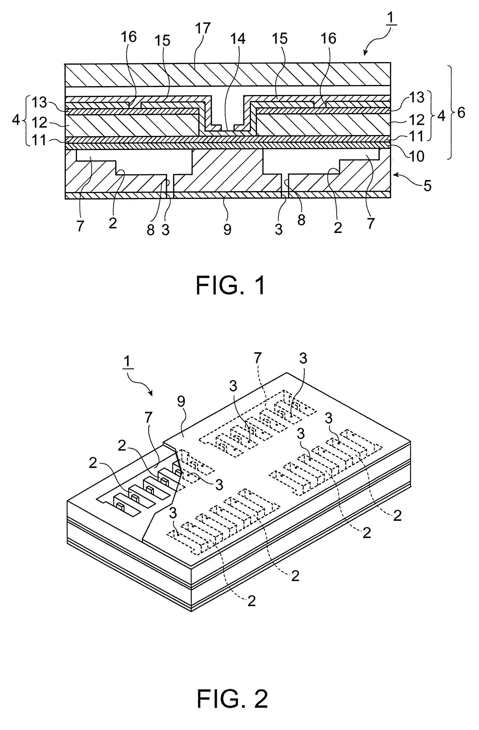
[0043]Preferred embodiments of the invention are described below. First, an inkjet head in accordance with an embodiment of the invention is described. FIG. 1 is a view of a major portion of an inkjet head in accordance with the embodiment, in other words, a view showing a major portion of a head chip. Reference numeral 1 in FIG. 1 denotes an inkjet head. The inkjet head 1 may be used for an inkjet printer, and is equipped with pressure chambers 2 that store ink, nozzles 3 that are provided at the pressure chambers 2 and eject the ink, and actuators 4 that change an internal pressure of the pressure chambers 2 to thereby eject the ink in the pressure chambers 2 through the nozzles 3.

[0044]Also, the inkjet head 1 is formed from a generally rectangular parallelepiped head chip or a plurality of head chips (not shown), each having a lower structure 5 forming a portion including the pressure chambers 2 and an upper structure 6 forming a portion including the actuators 4. The head chip i...


PUM

PropertyMeasurementUnit
Electrical conductoraaaaaaaaaa
Metallic bondaaaaaaaaaa
Internal pressureaaaaaaaaaa

Abstract

A method for manufacturing an inkjet head having a pressure chamber that stores ink, a nozzle that is provided at the pressure chamber and ejects the ink, and an actuator that changes an internal pressure of the pressure chamber to eject the ink in the pressure chamber through the nozzle. The method includes the steps of: forming the actuator on a substrate by using one of a liquid phase method and a vapor phase method to manufacture an upper structure; separating the upper structure from the substrate; forming a lower structure having the pressure chamber with metallic glass, independently of the substrate; and joining the upper structure and the lower structure.

Description

[0001]The entire disclosure of Japanese Patent Application No. 2006-070906, filed Mar. 15, 2006 is expressly incorporated by reference herein.BACKGROUND[0002]1. Technical Field[0003]The present invention relates to an inkjet head that ejects ink and a method for manufacturing an inkjet head.[0004]2. Related Art[0005]As inkjet heads used for inkjet printers, piezoelectric type inkjet heads and bubble type (thermal type) inkjet heads are known. These inkjet heads are provided with a pressure chamber that stores ink, and structured to push out and eject ink, by an actuator in the case of the piezoelectric type inkjet head, and by a bubble that is generated by boiling a solvent in the case of the bubble type inkjet head.[0006]Pressure chambers of the inkjet heads, for example, in the piezoelectric type and bubble type inkjet heads, are generally formed in a silicon substrate (silicon wafer) by a semiconductor process. Reasons for forming pressure chambers in a silicon substrate are beca...

Claims


Application Information

Patent Timeline
IPC IPC(8): H04R17/00H01L41/22B41J2/14B41J2/16
CPCB41J2/161Y10T29/42B41J2/1631B41J2/1637B41J2/1642B41J2/1643B41J2/1646H01L41/1876H01L41/318H01L41/319Y10T29/4913Y10T29/49401Y10T29/49126Y10T29/49128Y10T29/49155B41J2/1628H10N30/8554H10N30/078H10N30/079
Inventor FURUYA, NOBORU
Owner SEIKO EPSON CORP
Learn More