Eureka AIR delivers breakthrough ideas for toughest innovation challenges, trusted by R&D personnel around the world.

Potentiometric measuring chain

Inactive Publication Date: 2007-09-20
SI ANALYTICS GMBH
View PDF6 Cites 1 Cited by
  • Summary
  • Abstract
  • Description
  • Claims
  • Application Information

AI Technical Summary

Benefits of technology

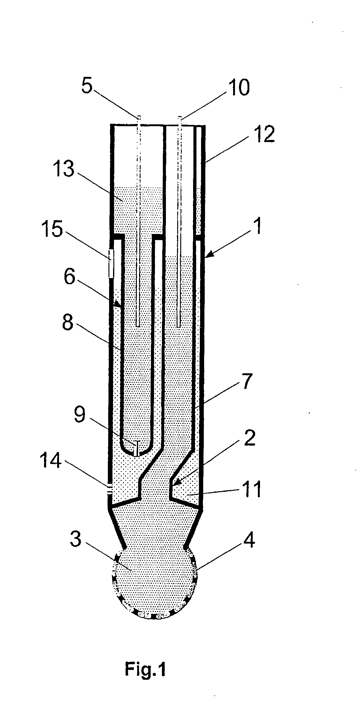
[0010] The object of the invention is therefore to find a pH measuring chain having a I3− / I− reference electrode of the Ross™ type that is simple to manufacture and that has a longer lifetime.

Problems solved by technology

A disadvantage compared with the conventional Ag / AgCl electrode is the shorter lifetime.
Although the lifetime of the system is distinctly increased by those measures, permanent stabilisation of the system is not possible.
Furthermore, the expenditure in terms of production engineering for the manufacture of such a system is relatively high.

Method used


Image

  • Potentiometric measuring chain
  • Potentiometric measuring chain
  • Potentiometric measuring chain

Examples


example

[0032]FIGS. 5a to 5c show extracts from a long-time test with various measuring chains.

[0033] The Ross Ultra™ measuring chain is a commercially available I3− / I− measuring chain (model Orion 81-01U Ross Ultra™, made by: Thermo Electron Corporation, Waltham, Mass., USA), and measuring chains 505 A and 505 B are two different forms of a measuring chain according to the invention.

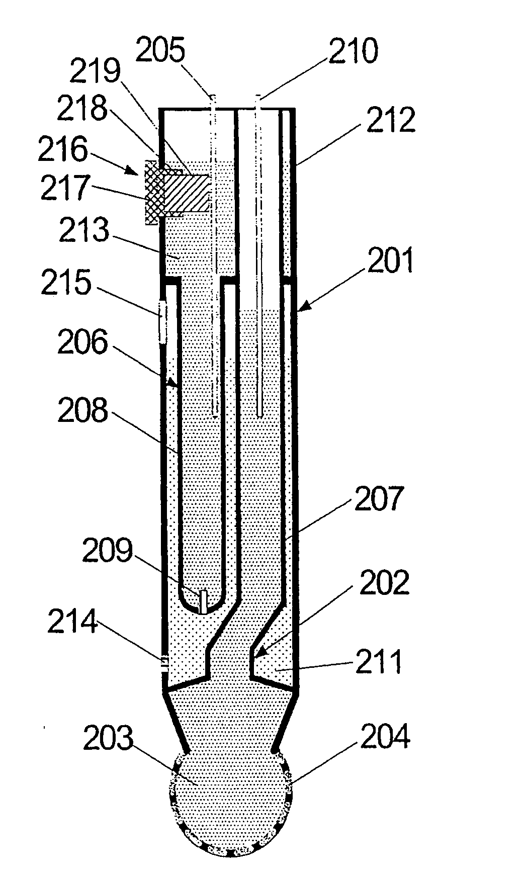
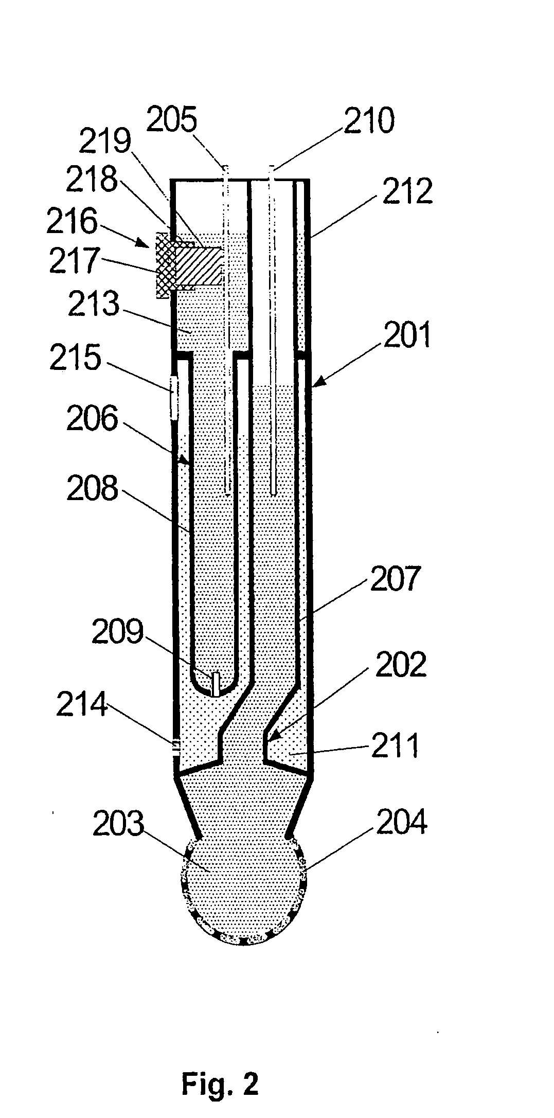
[0034] The measuring chains 505 A and 505 B according to the invention were constructed analogously to FIG. 3. The outlet conduits 305 and 310 consisted of platinum. The measuring chains were filled with the following solutions as shown in Tables 1 and 2:

TABLE 1ratio505 A[I−] in mol / l[I3− / I−]3pHKCl in mol / lreference3.80.009electrolyteinternal2.80.017.00electrolytebridge0.53.0electrolyte

[0035]

TABLE 2ratio505 B[I−] in mol / l[I3− / I−]3pHKCl in mol / lreference3.80.0005electrolyteinternal2.80.016.40electrolytebridge0.253.0electrolyte

[0036] Measuring chain 505 A contained a single storage body 319. The storage body ...


PUM


Abstract

An ion-selective potentiometric measuring chain having the I3− / I− redox system as the reference electrolyte is described, in which the components of the reference electrolyte that determine the potential are regenerable. In particular, iodine or I3− / I− solution can be released in a controlled manner from a body situated in the reference electrolyte.

Description

BACKGROUND OF THE INVENTION [0001] 1. Field of the Invention [0002] The invention relates to an ion-selective potentiometric measuring chain of two potentiometric electrodes, especially for determining pH value, which electrodes are combined, where appropriate, to form a one-piece construction. [0003] 2. Description of Related Art [0004] A measuring chain of that kind consists of a measuring electrode and a reference electrode. Both electrodes may be combined in a single-rod measuring chain. [0005] The measuring electrode has at its end a membrane that is ion-sensitive towards the ionic species to be determined, is filled with a buffered internal electrolyte and contains an outlet conduit consisting of an inert, electrically conductive material, for example gold, platinum, palladium, iridium or alloys with those metals. [0006] The reference electrode has at its end a porous body, the diaphragm, which makes the electrically conductive connection to the measurement medium. The referen...

Claims


Application Information

Patent Timeline
IPC IPC(8): G01N27/26
CPCG01N27/4035G01N27/333G01N27/38G01N27/44
Inventor TAUBER, GUNTER
Owner SI ANALYTICS GMBH
Why Eureka
Eureka Blog
Learn More