Apparatus and method for microwave processing of materials

a technology of material processing and microwave energy, applied in microwave heating, electrical apparatus, electric/magnetic/electromagnetic heating, etc., can solve the problems of large deviation from the relatively uniform power distribution, significant non-uniformity in spatial power density of multi-mode cavity operating at fixed frequency, undesirable power concentration, etc., to achieve uniform microwave energy application, reduce the cost of microwave power source, and minimize the energy concentration in the near vicinity of waveguide entrance.

Inactive Publication Date: 2007-09-20
HICKS KEITH R +4
View PDF17 Cites 54 Cited by
  • Summary
  • Abstract
  • Description
  • Claims
  • Application Information

AI Technical Summary

Benefits of technology

[0016] Objects of the present invention include: providing a microwave heating apparatus in which a workpiece may be subjected to a controlled application of microwave energy; providing a microwave heating apparatus in which various workpieces may be processed uniformly despite differences in their load characteristics; providing a microwave heating apparatus in which energy concentrations in the near vicinity of the waveguide entrance are minimized; providing a microwave heating apparatus in which a plurality of workpieces may be subjected to a more uniform application of microwave energy using a relatively lower cost microwave power source; providing a method of applying a controlled concentration of microwave energy to a workpiece of a desired size and shape; providing a method of uniformly processing a workpiece with microwave energy despite discontinuities on the workpiece itself; and, providing a method of microwave heating in which a leaky subcavity creates a relatively uniform power density within a microwave processing cavity when used with a relatively narrow bandwidth microwave generator.
[0017] Other objects and advantages will be accomplished by the present invention, which is designed to allow dispersion of the microwaves introduced into a furnace cavity for heating or other selected processes. Some applicable processes include cooking, heat treatment, sterilization, sintering, plasma processing, ore processing, polymerization, etching, and preparing films.
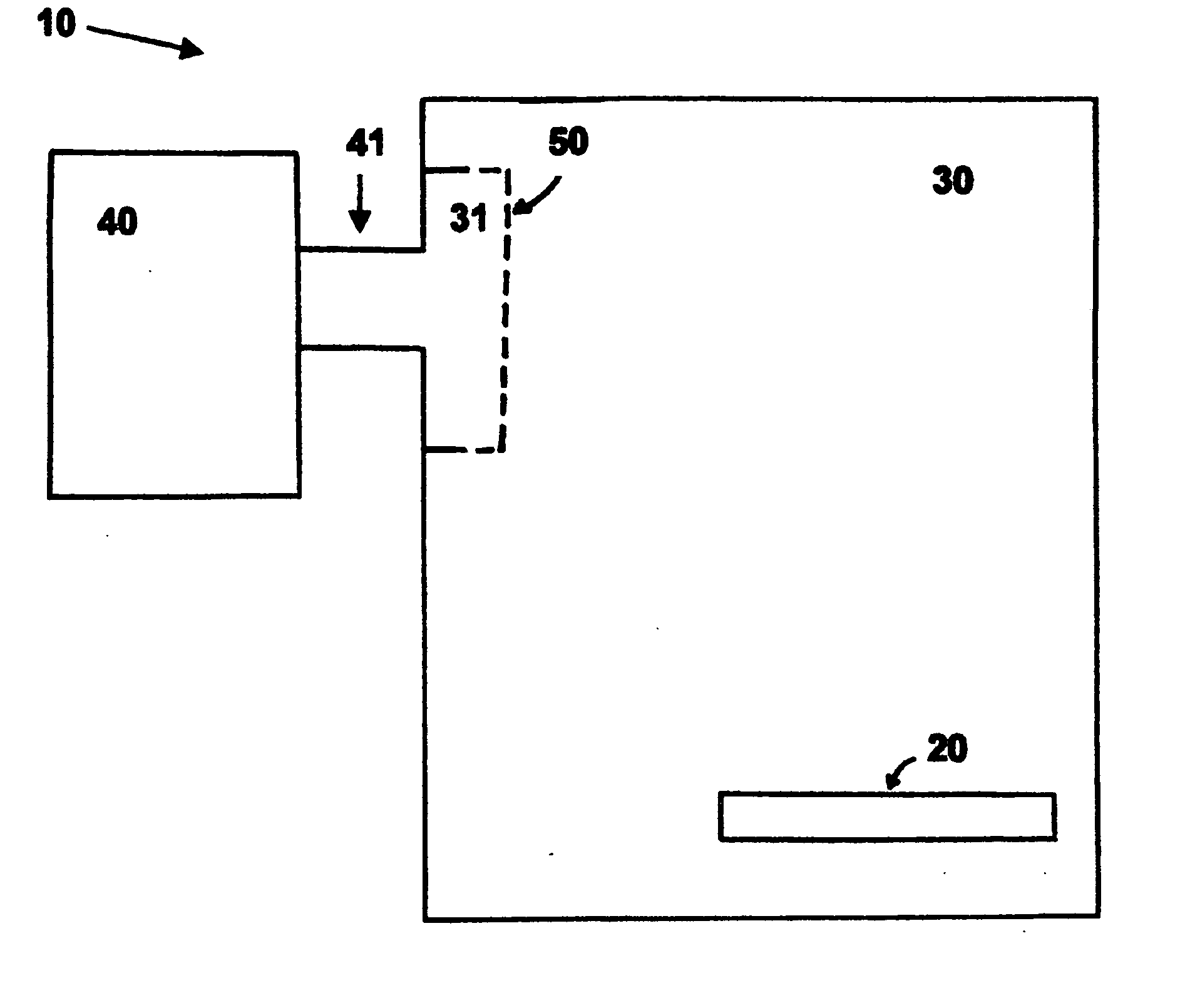
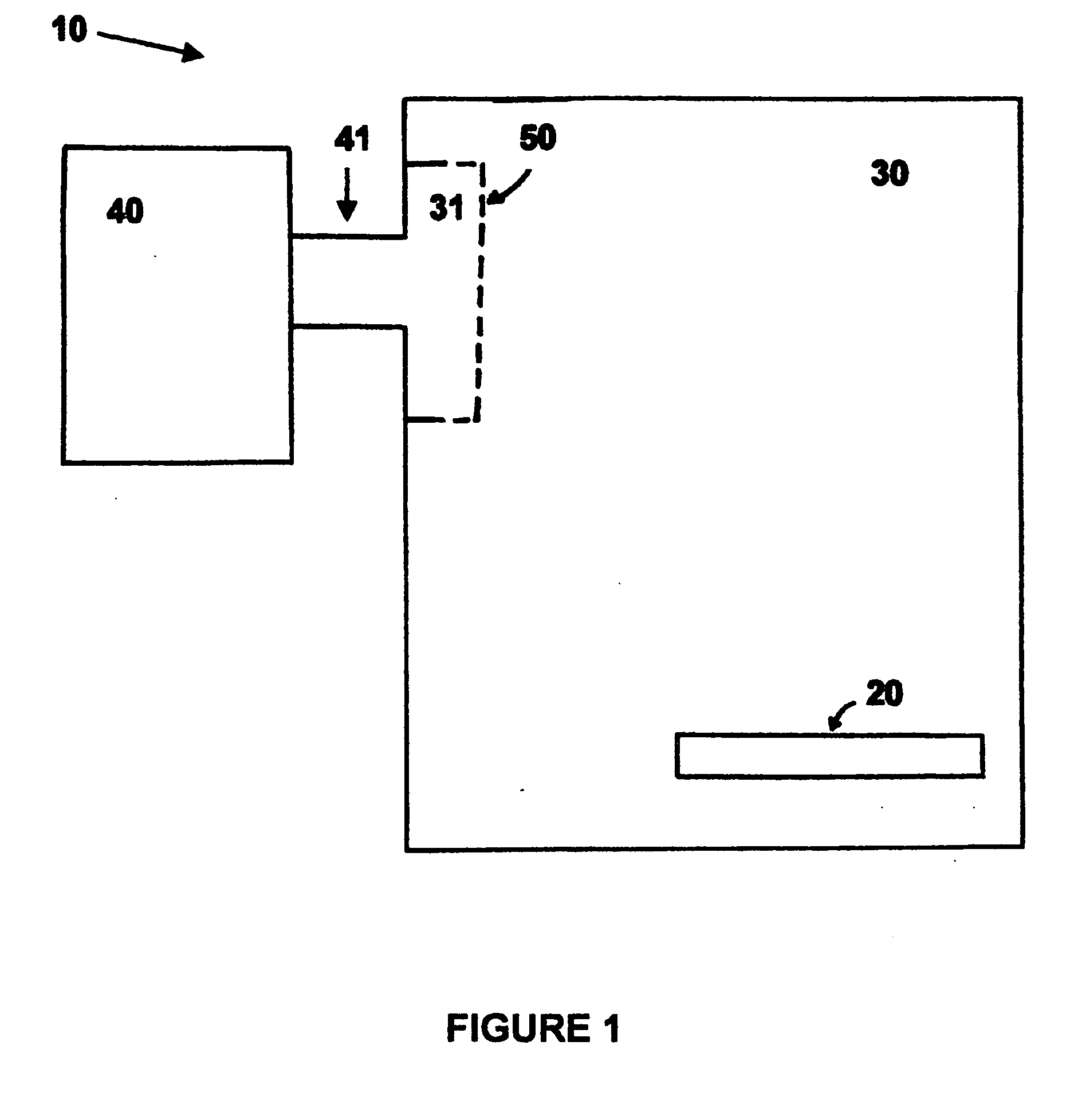
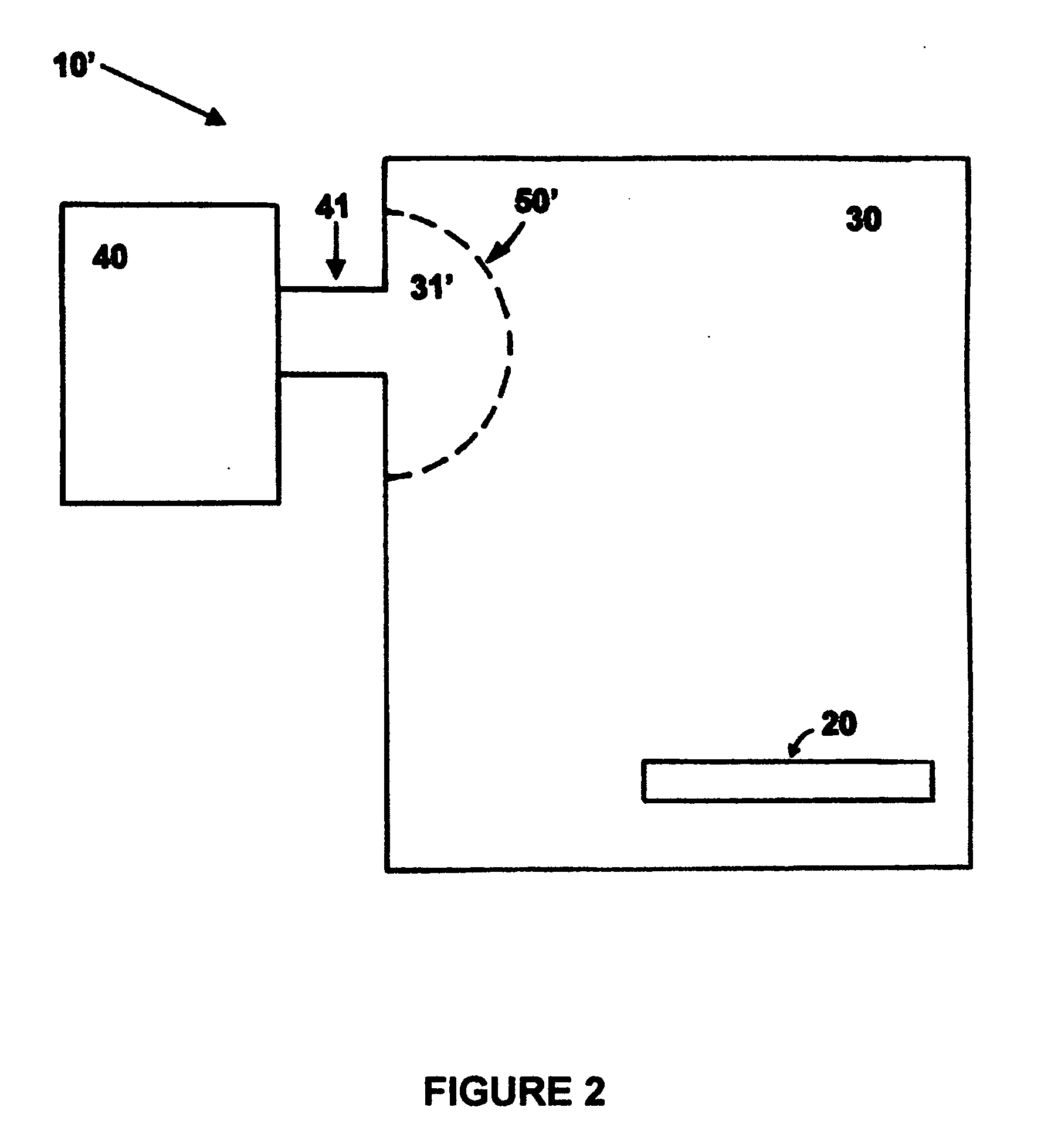
[0018] According to one aspect of the invention, an apparatus for microwave processing of selected materials comprises: a microwave source having a selected frequency range of a few percent or less; a multimode applicator cavity; a transmission line from the microwave source to the microwave cavity, the transmission line including a waveguide opening into a first wall of the cavity; and, a metallic structure enclosing a selected volume of the cavity around the waveguide opening, the structure and the first wall defining the boundary of a multimode subcavity, the boundary surface being partially reflective and partially transmissive to microwave energy, whereby the microwave power may be introduced more uniformly into the applicator cavity.
[0019] According to another aspect of the invention, a method for microwave processing of selected materials comprises the steps of: (a) placing the material in a multimode microwave applicator cavity, the cavity containing a subcavity having a boundary that is partly reflective and partly transmissive to microwave energy; and, (b) introducing microwave energy having a bandwidth of a few percent or less into the subcavity from which the microwave energy can pass through the partially transmissive boundary and into the applicator cavity, whereby the material may be more uniformly exposed to microwave energy.

Problems solved by technology

However, it is well known that a multimode cavity operating at fixed frequency will display significant non-uniformities in the spatial power density owing to the formation of standing waves (or the excitation of only a small number of microwave modes within the cavity).
However, Applicants later discovered that there are some deviations from the relatively uniform power distribution predicted by modeling and observed in simple cavity characterization tests.
The net result is that there is often an undesirable concentration of power immediately adjacent to the waveguide entrance.
In the present circumstances, this assumption is not satisfied, making it impossible to model the performance of a leaky waveguide in the multimode cavities of interest here.
However, the use of a slotted waveguide was investigated (as will be described later) and was found not to provide beneficial uniformity improvements, particularly as compared to the inventive structures.

Method used


Image

  • Apparatus and method for microwave processing of materials
  • Apparatus and method for microwave processing of materials
  • Apparatus and method for microwave processing of materials

Examples


example 1

[0051] To examine the effect of bandwidth on uniformity in conjunction with the inventive subcavity, a series of tests were performed using a MicroCure™ 2100 oven as described previously. A rectangular plate of uniformly lossy material was used as a test load, and in each run the plate was heated for 10 seconds at 200 W forward power, after which it was removed and immediately photographed with an IR thermal imaging camera to map the temperature distribution across its surface. All runs used a center frequency of 6.425 GHz, and frequency sweeps (±about the center frequency) of 0, 0.1438, 0.2875, or 0.575 GHz respectively.

[0052] With no subcavity installed, at fixed frequency the thermal distribution was highly nonuniform, with several distinct hot spots and a temperature range of 25-60° C. The uniformity gradually improved as bandwidth was increased and the temperature range narrowed to about 26-40° C.

[0053] The runs were then repeated using a “slanted box” subcavity as shown in F...

example 2

[0057] An applicator 71 was constructed with internal dimensions of 20″ diameter×36″ high. This applicator further had flat surfaces about 6″ wide running lengthwise at various locations around its circumference to provide convenient attachment points for the input waveguides. A cylindrical perforated metal sheet 55 approximately 11″ diameter×36″ high was placed inside, thereby forming a subcavity 34 having a generally annular shape. The diameter of this perforated plate was chosen to accommodate the outside dimensions of a wafer boat 72 holding 25 standard 8″ silicon wafers 73 (several of which are shown in the drawing). Microwave power was supplied by three 700 W C-band amplifiers 40 and fed through three separate waveguides 41 (two of which are shown for simplicity). Thus, all of the microwave power was launched into the same annular subcavity, but at several locations around the circumference and at different heights as indicated schematically in the figure. Three separate proce...

example 3

[0060]FIG. 10 shows a generally cylindrical applicator 71 with a generally annular subcavity 34 similar to that in EXAMPLE 2. Microwave power enters through one or more slotted waveguides 74 that run lengthwise within the subcavity 34. Thus, the slots 75 provide a first means of distributing energy, by providing multiple launch points along the length of the subcavity. The perforated boundary 55 of the subcavity 34 then provides a second means of further dispersing this energy so that greater uniformity may be achieved, as suggested by consideration of the schematic radiation patterns indicated in FIGS. 8A and 8C.

[0061] The apparatus shown in FIG. 10 has slotted waveguides running axially at several locations around the circumference of the cavity, with slots at various heights. Those skilled in the art will appreciate that a similar effect may be achieved by arranging several slotted waveguides running circumferentially (each at a different height). In this case, the slots would s...


PUM


Abstract

A microwave heating apparatus is designed to improve distribution of the microwaves introduced into a multi-mode microwave cavity for heating or other selected applications. The microwave heating apparatus includes a microwave signal generator and a waveguide to convey microwave power to the cavity. A perforated metal plate disposed within the cavity encloses a volume adjacent to the waveguide opening, forming a leaky multimode subcavity. Through multiple processes of reflection, transmission, diffraction, and scattering, the leaky subcavity serves to smooth the microwave power distribution in the near-field region adjacent to the waveguide to better disperse the energy throughout the main applicator cavity. A more uniform level of microwave power is thereby applied to the workpiece.

Description

BACKGROUND OF THE INVENTION [0001] 1. Field of the Invention [0002] This invention relates to the field of microwave radiation. More specifically, this invention relates to a microwave furnace having improved heating uniformity throughout the applicator cavity by use of a leaky multimode subcavity within the main microwave cavity. [0003] 2. Background Art [0004] In the field of microwave radiation, it is well known that microwave furnaces are typically constructed with a fixed operating frequency. Most microwave sources have a very narrow bandwidth because they employ a resonant cavity. Microwave ovens constructed for home use are provided with a magnetron that operates at 2.45 GHz, the frequency that has been allocated by the FCC for microwave heating and similar applications. Owing to the coupling ability of a 2.45 GHz microwave to water, these ovens are used for cooking foods, drying, and other purposes wherein the principal material to be acted upon is water. However, it is well...

Claims


Application Information

Patent Timeline
Patent Type & Authority Applications(United States)
IPC IPC(8): H05B6/74
CPCH05B6/74H05B6/704
Inventor HICKS, KEITH R.AHMAD, IFTIKHARDECAMILLIS, CLAYTON R.WANDER, JOSEPH M.FATHI, ZAKARYAE
Owner HICKS KEITH R
Why Eureka
Try Eureka