
Laser machining device, laser machining method, and thin sheet machined using same

A laser processing method and laser processing technology, applied to laser welding equipment, metal processing equipment, manufacturing tools, etc., can solve the problems of laser beam blur, processing speed limit, and difficulty in forming through holes, etc., to achieve uniform power density and increase Processing speed, the effect of shortening the focal length

Inactive Publication Date: 2020-03-31
外而得株式会社
View PDF19 Cites 0 Cited by
  • Summary
  • Abstract
  • Description
  • Claims
  • Application Information

AI Technical Summary

Problems solved by technology

[0012] However, in an apparatus that irradiates a laser beam on a sheet attached to a cylindrical roll to form through holes, continuous processing cannot be performed, and processing is performed on a sheet-by-sheet basis, so it is necessary to frequently replace the sheet and process There is a limit to the increase in speed
[0013] In addition, in the laser processing method in which a flexible long substrate is conveyed on the outer periphery of a translucent hollow reel and the focus of pulsed light irradiated from the hollow side of the hollow reel is moved in the axial and / or circumferential direction, the In the case of matrix-like drilling of long substrates, it is necessary to alternately and intermittently control the linear reciprocating motion of the laser device in the axial direction and the control of conveying the long substrate in the direction of the roll. There is a limit
[0014] In addition, in order to form a periodic structure on the inner peripheral surface of the cylinder, by using a condenser lens and a reflection mirror, the pulsed light introduced from the axial direction to the inner side of the cylinder travels radially outward, and the reflection mirror The rotation of the cylinder, the rotation of the cylinder, and the laser processing method of moving in the axial direction, in the case of performing a matrix-like drilling process on the inside of the cylinder, it is necessary to alternately and intermittently carry out the linear movement of the cylinder in the axial direction. The control of reciprocating motion, the control of rotating the cylinder, and the control of rotating the cylinder and the mirror have limitations in improving the processing speed.
[0015] Furthermore, in a general method for scanning a laser beam using a rotating polygon mirror or a galvano mirror for forming through holes in a matrix, in order to form an image of the laser beam scanned at an equal angle by the rotating polygon mirror on a thin plate and For constant speed scanning, although the fθ lens is used, the problem is that if the diameter of the incident light entering the fθ lens is increased, the laser beam will be blurred on the thin plate. On the contrary, if the incident light path entering the fθ lens is reduced, then Increased beam diameter on thin plates
[0016] In addition, when the focal length is increased to reduce the swing angle from the fθ lens, the problem of increasing the beam diameter also occurs, making it difficult to form uniform through-holes.
[0017] In addition, in such a method, the power density of the laser beam varies depending on the processing part, so there is a problem that burrs are generated around the formed through-hole at the part where excessive energy is applied.

Method used


Image

  • Laser machining device, laser machining method, and thin sheet machined using same
  • Laser machining device, laser machining method, and thin sheet machined using same
  • Laser machining device, laser machining method, and thin sheet machined using same

Examples


Embodiment 1

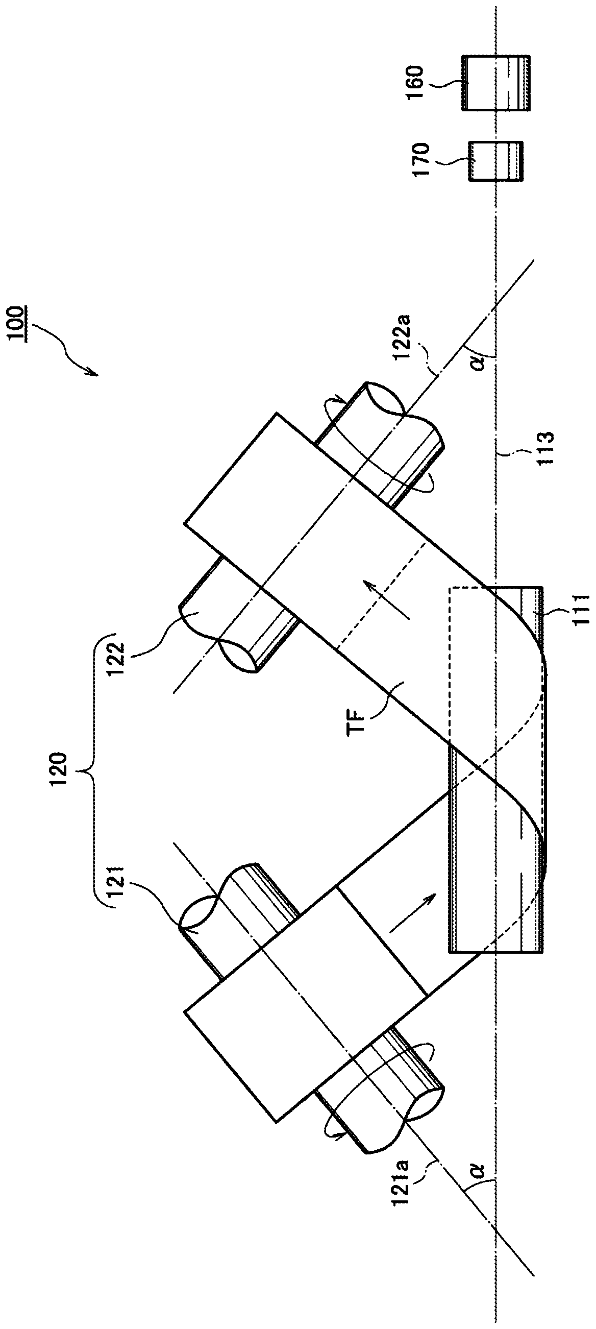
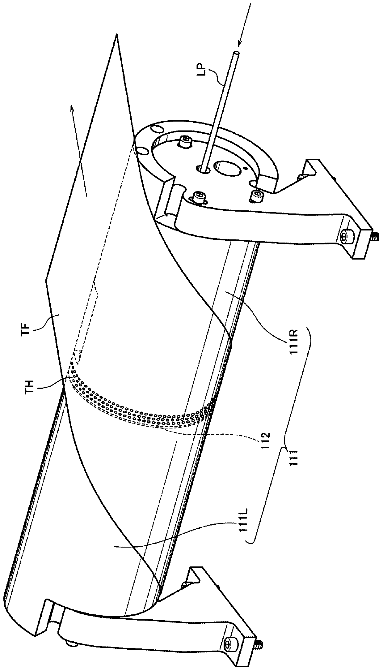
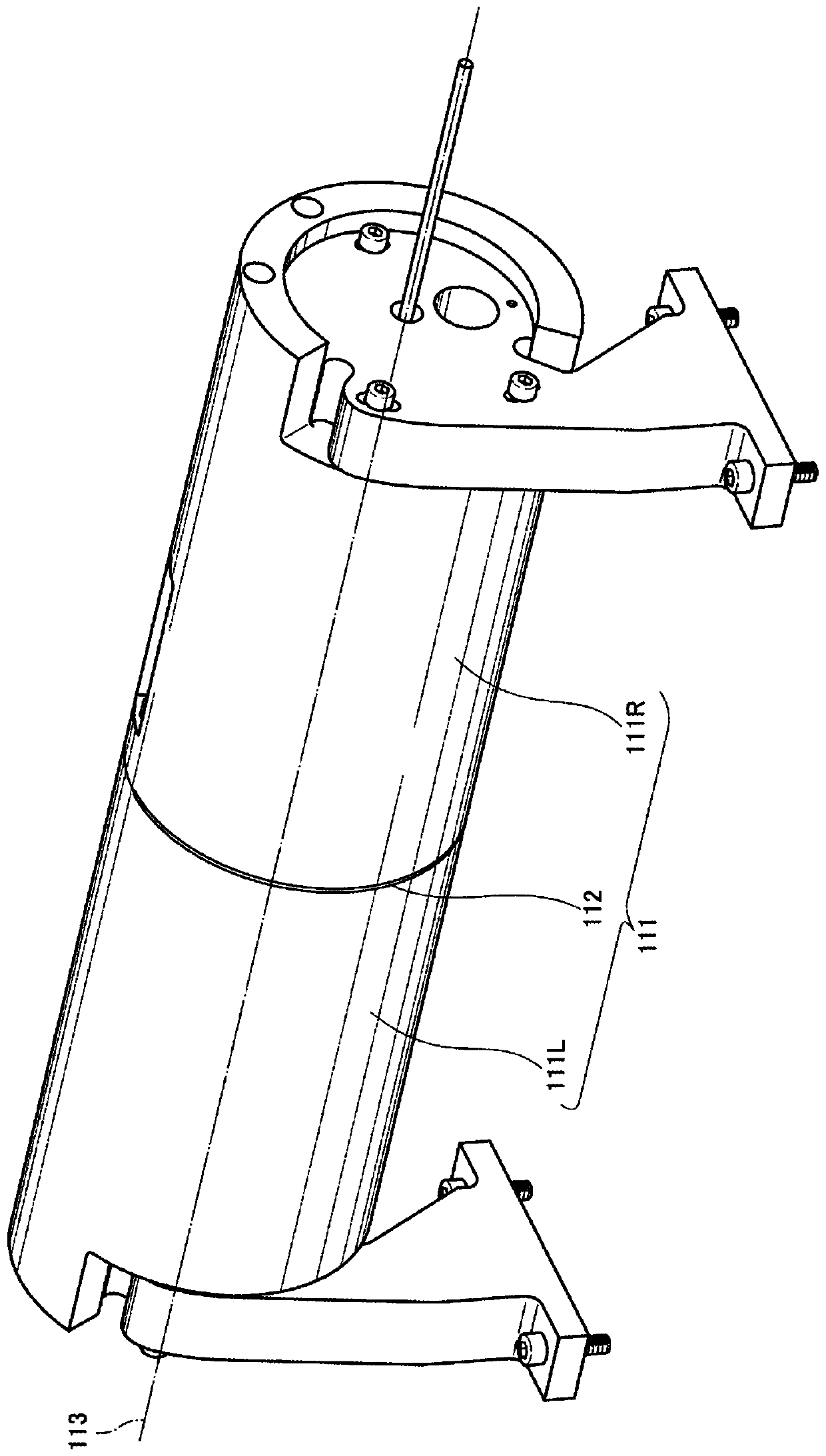
[0127] The laser processing device of the first embodiment of the present invention, together with the laser processing method and the long thin plate after laser processing, is based on Figure 1 to Figure 6 Be explained.

[0128] here, figure 1 is a schematic diagram of the laser processing device of the first embodiment of the present invention, figure 2 is a diagram showing the relationship between the cylindrical body and the thin plate in the first embodiment of the present invention, image 3 It is a figure which shows the appearance of the cylindrical body of the 1st Example of this invention, Figure 4 It is a figure which shows the structure of the opening part of the cylindrical body of the 1st Example of this invention, Figure 5 is a diagram showing the arrangement of reflective members according to the first embodiment of the present invention, Figure 6 It is a figure which shows the route and irradiation range of the pulsed light of the laser processing ap...

Embodiment 2

[0157] Next, with regard to the laser processing device of the second embodiment of the present invention, together with the laser processing method and the long thin plate after laser processing, based on Figure 7 ~ Figure 10 Be explained.

[0158] here, Figure 7 is a diagram showing the relationship between the cylindrical body and the thin plate in the second embodiment of the present invention, Figure 8 It is a figure which shows the appearance of the cylindrical body of the 2nd Example of this invention, Figure 9 It is a figure which shows the structure of the opening part of the cylindrical body of the 2nd Example of this invention, Figure 10 It is a figure which shows the other structure of the opening part of the cylindrical body of 2nd Example of this invention.

[0159] In addition, regarding the configuration of devices other than the slit fitting 214, the inner slit 215, the roller engaging bolt 216, the roller engaging pin 217, and the inspection window 21...


PUM


Abstract

Provided are a laser machining device that improves the machining speed and forms uniform and high-precision through-holes when performing a process for forming fine through-holes in a matrix shape inan elongated thin sheet, a laser machining method, and a thin sheet in which through-holes are formed in a matrix shape using such laser machining. A laser machining device (100) comprising: a cylindrical body (111) having an opening (112) in the circumferential surface thereof, a thin sheet (TF) to be machined being diagonally wound on the cylindrical body (111); a thin sheet transferring means(120) that transfers the thin sheet (TF) wound on the cylindrical body (111) along the longitudinal direction of the thin sheet (TF); a motor (130) having a rotation axis (130a) disposed coaxially with the center axis (113) of the cylindrical body (111); a reflection member (140) secured to a rotation shaft rod (131) of the motor (130); and a laser light emission means (160) that emits pulse light(LP); through-holes being continuously opened in the thin sheet (TF).

Description

technical field [0001] The present invention relates to a laser processing device / laser processing method for forming a matrix of tiny through-holes on a long thin plate and a long thin plate that has been laser processed, and particularly relates to the drilling of a gas diffusion layer for a fuel cell and a storage battery. Laser processing technology and molded products of thin plates used in current collectors, etc. Background technique [0002] Conventionally, in the case of processing to form minute through-holes on a thin metal plate, an etching process utilizing a chemical reaction has been widely used. [0003] However, the major problem of forming through-holes in thin metal plates by etching is that the shape of the through-holes is unstable, the number of steps is large and the processing cost is high because of the wet process, and it is difficult to form through-holes of 100 μm or less. It is difficult to increase the processing speed, etc. [0004] In additi...

Claims


Application Information

Patent Timeline
Patent Type & Authority Applications(China)
IPC IPC(8): B23K26/382B23K26/08
CPCB23K26/382B23K26/0846B23K26/0838B23K26/08
Inventor 山川明郎杣直彦兼古光行
Owner 外而得株式会社
Learn More