

Electro-optical device and electronic apparatus
a technology of optical devices and electronic devices, applied in the direction of static indicating devices, identification means, instruments, etc., can solve the problems of inefficient incident of light on the intrinsic layer, increased man-hours and costs, and inability to efficiently generate photogenerated charges, etc., to achieve efficient incident and sufficient light sensitivity
- Summary
- Abstract
- Description
- Claims
- Application Information
AI Technical Summary
Benefits of technology
Problems solved by technology
Method used
Image

Examples
first exemplary embodiment
[0035]First, the overall structure of the electro-optical device according to the first exemplary embodiment will be described with reference to FIGS. 2 to 4.
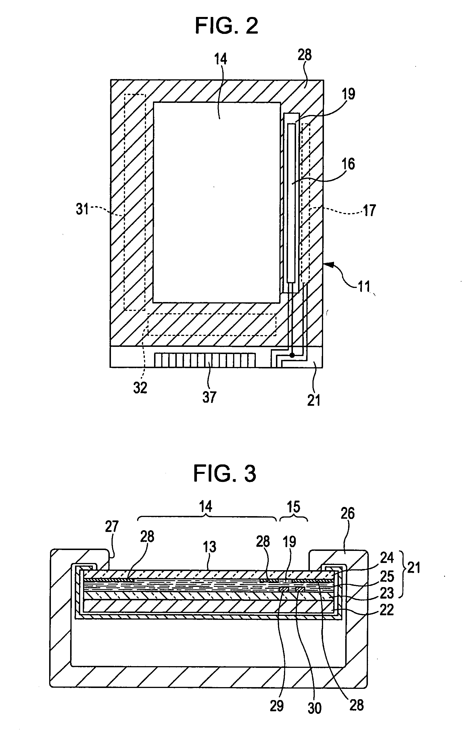
[0036]In FIG. 2, the electro-optical device 11 includes a display panel 21 including two substrates stuck together. In the case of FIG. 3, a liquid crystal panel is employed as the display panel 21. In this case, the electro-optical device 11 includes the display panel 21 and an illuminating unit 22. A self-luminous display panel can also be employed as the electro-optical device. In this case, no illuminating unit is necessary.
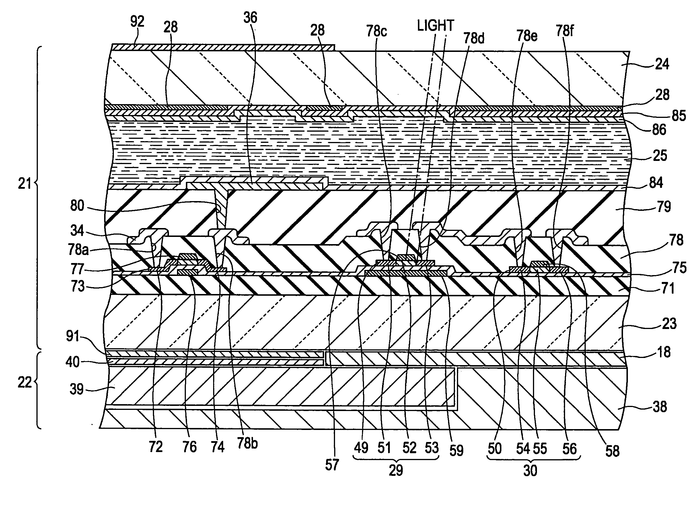
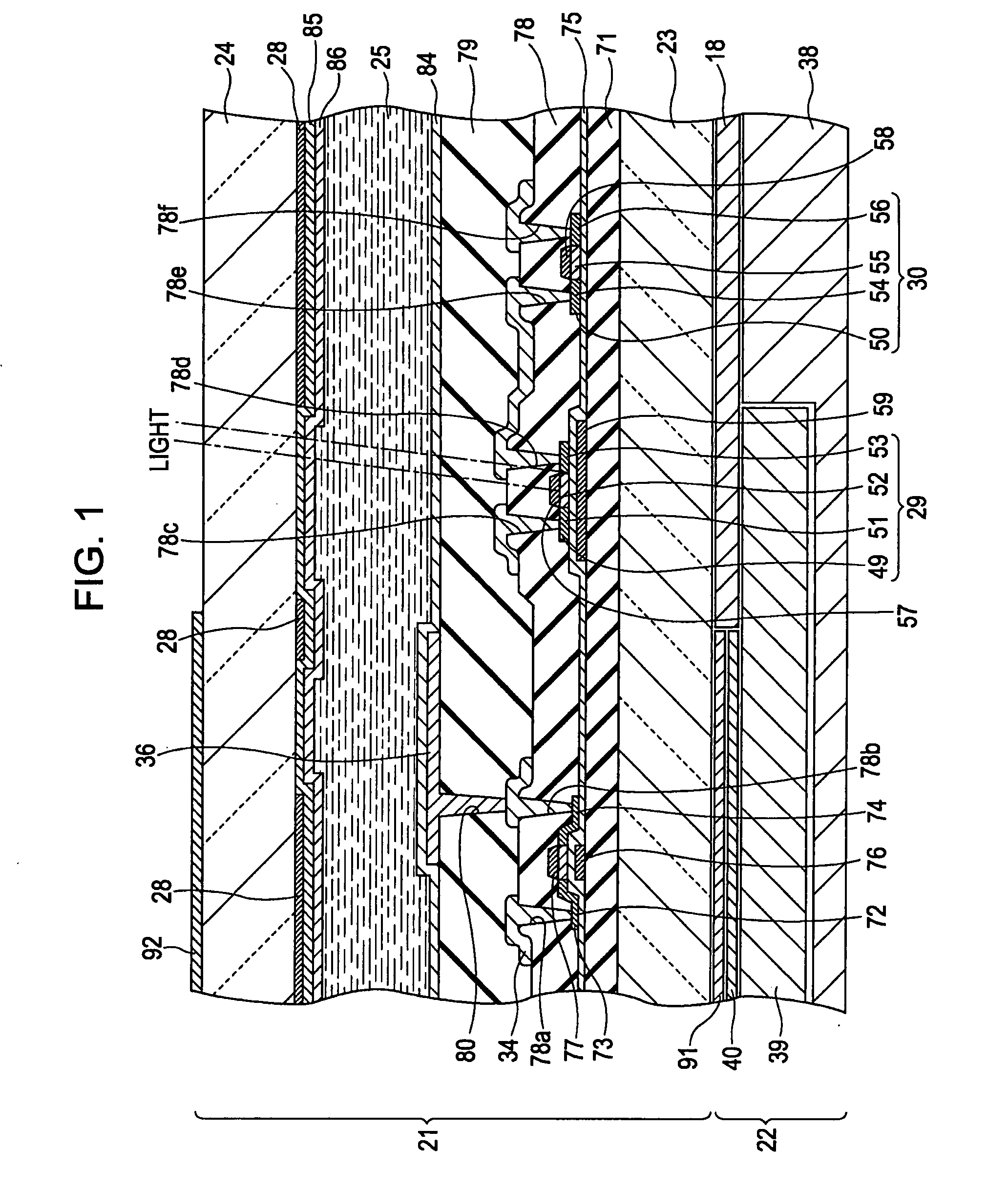
[0037]As shown in FIG. 3, the display panel 21 includes a light-transmitting element substrate 23, a light-transmitting opposing substrate 24, and liquid crystal 25 enclosed therebetween. The element substrate 23 and the opposing substrate 24 facing each other are stuck together with a sealing material (not shown). The display panel 21 includes, for example, a plurality of scanning lines 33 extending in ...
second exemplary embodiment
[0082]FIG. 6 is a perspective view schematically showing the electro-optical device according to a second exemplary embodiment of the invention. In FIG. 6, the same reference numerals will be used to designate the same components as those in FIG. 1, so that the description will be omitted.
[0083]The reflectors 59 in the first exemplary embodiment are formed of metal and are in a floating status. Therefore, an unforeseen parasitic capacity is generated between the cathode (N-type region 51) of each PIN diode 29 and the corresponding reflector 59 and between the anode (P-type region 53) of each PIN diode 29 and the corresponding reflector 59. In addition, the reflectors 59 can be charged with static electricity. In this case, the electrical impact due to the reflectors 59 is brought on the anodes and cathodes of the PIN diodes 29. In this case, by extending each reflector 59 up to under the corresponding anode and up to under the corresponding cathode in the same manner, the electrical...
PUM
 Abstract
Description
Claims
Application Information