Spark plug for internal combustion engine and related manufacturing method

a technology for spark plugs and internal combustion engines, applied in the manufacture of spark plugs, spark plugs, machines/engines, etc., can solve the problems of increased thermal stress of spark plugs of related art, large number of fabricating steps to be performed, and difficulty in having adequate bonding capability, so as to suppress the adverse effects of porcelain insulators and increase thermal stress

Inactive Publication Date: 2007-09-20
DENSO CORP
View PDF3 Cites 14 Cited by
  • Summary
  • Abstract
  • Description
  • Claims
  • Application Information

AI Technical Summary

Benefits of technology

[0059]That is, in general, with the center electrode base material body having the diameter greater than 2.5 mm, a drop is liable to occur in bonding capability between the center electrode base material body and the Ir alloy tip. Therefore, applying the present invention to such a spark plug allows the spark plug to have advantageous effects of the present invention.
[0060]Furthermore, with the spark plug for the internal combustion engine of the present embodiment, the Ir alloy tip may be preferably bonded to the center electrode base material body at a joint portion where a fused layer is formed with an unfused portion being formed inside the fused layer in a width F in a correlation with the diameter A of the circumscribed circle CA of the Ir alloy tip under the relationship expressed as F≦0.2×A.
[0061]In such a case, an increased thermal stress is prevented from concentrating on the unfused area, ensuring bonding capability between the center electrode base material body and the Ir alloy tip.
[0062]Moreover, with the spark plug for the internal combustion engine of the present embodiment, the Ir alloy tip may be preferably bonded to the center electrode base material body at a joint portion formed with a fused layer having an entire circumference spaced from a bore end of a through-bore of the

Problems solved by technology

If the contours of the Ir alloy tip and the center electrode base material body exposed to the laser beam irradiating position are irregular, a joint portion between the Ir alloy tip and the center electrode base material body is fused in an uneven fusing pattern with the resultant difficulty of having adequate bonding capability.
However, a large number of fabricating steps need to be performed for processing the Ir alloy tip in a precisely columnar shape.
As a result, the spark plug of the related art suffers from increased thermal stres

Method used


Image

  • Spark plug for internal combustion engine and related manufacturing method
  • Spark plug for internal combustion engine and related manufacturing method
  • Spark plug for internal combustion engine and related manufacturing method

Examples


first embodiment

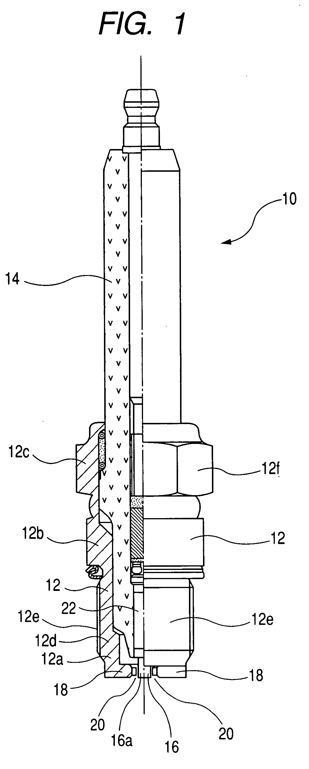
[0134]A spark plug of a first embodiment according to the present invention is described below in detail with reference to FIG. 1 to 14 of the accompanying drawings.

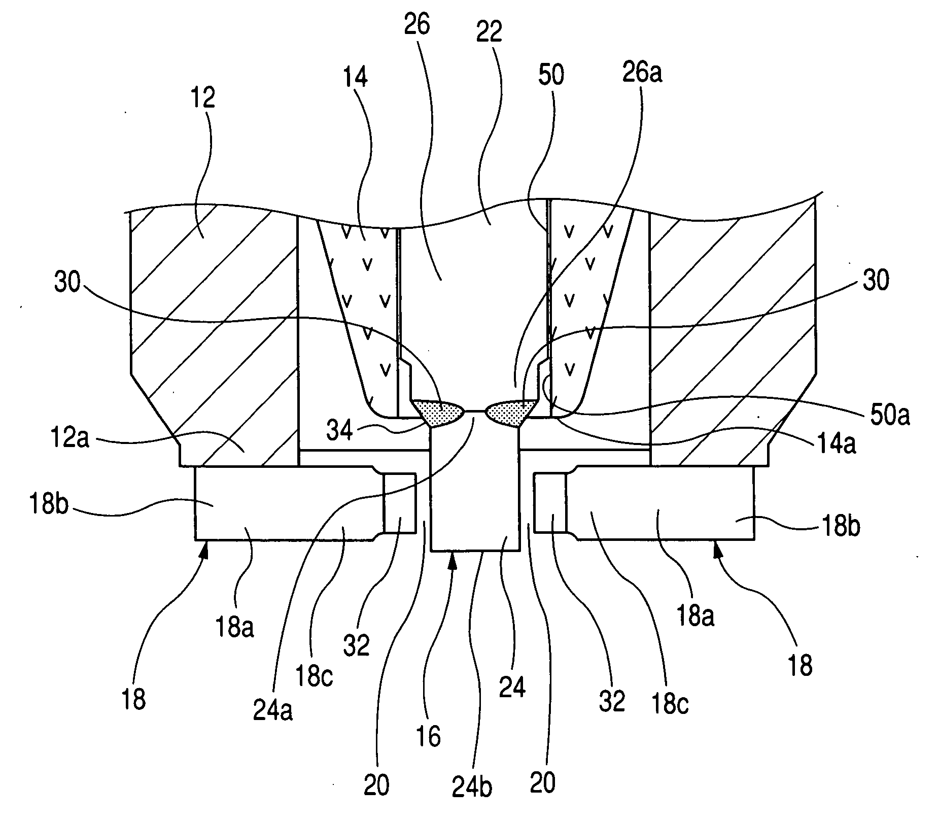
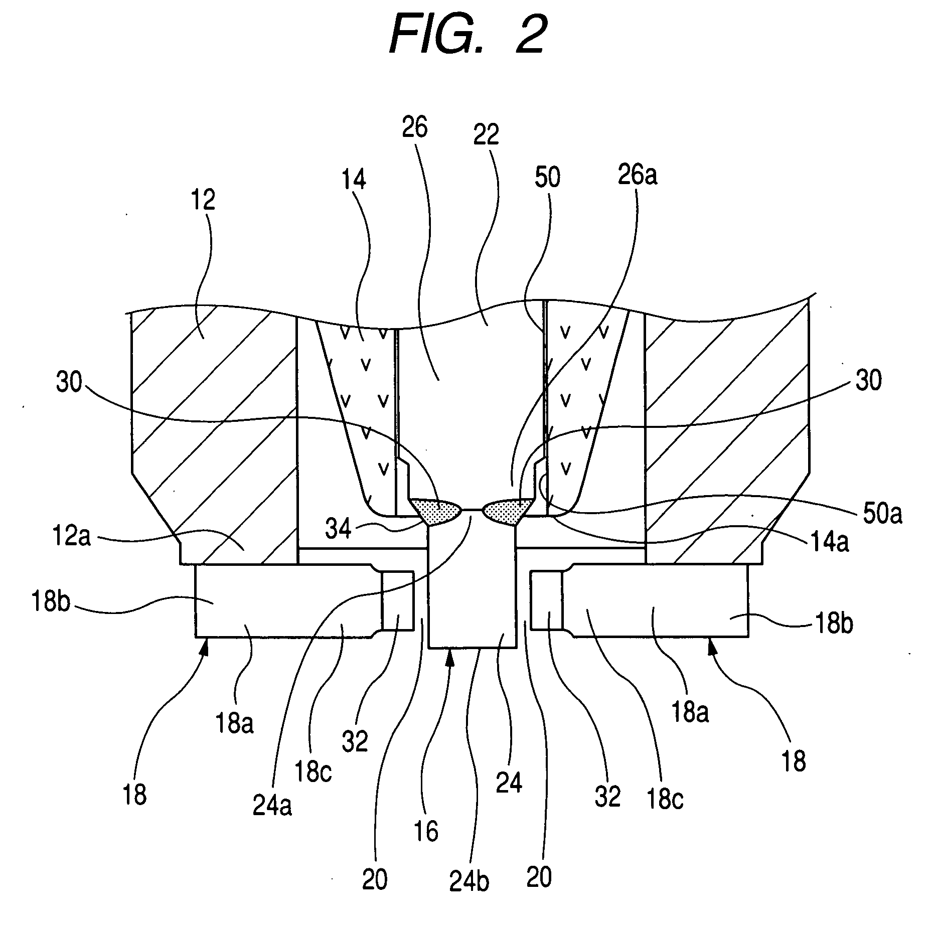
[0135]As shown in FIGS. 1 to 3, the spark plug 10 of the present embodiment comprises a cylindrical metal shell 12, an porcelain insulator 14 fixedly held with the cylindrical metal shell 12 and extending in a central axis thereof, a center electrode 16 fixedly supported with the porcelain insulator 14 in a central axis thereof, and ground electrodes 18 fixedly bonded to a leading end 12a of the cylindrical metal shell 12 to provide spark discharge gaps 20 with respect to a leading end 16a of the center electrode 16.

[0136]The cylindrical metal shell 12 includes an intermediate body 12b, an upper section 12c and a lower section 12d. The upper section 12c has an outer circumferential periphery formed in a hexagonal shape and acting as a tool-fitting section 12f. The lower section 12d of the cylindrical metal shell 12 has a...

second embodiment

[0186]A spark plug 10C of a second embodiment according to the present invention is described below with reference to FIGS. 16 to 20.

[0187]The spark plug10C of the present embodiment differs from the gas sensor 1 of the first embodiment in that the spark plug 10C includes a center electrode 16C having an Ir alloy tip 24C, formed in a substantially square shape in cross section on a plane perpendicular to an axis of the center electrode 16C, which has flat side surfaces 60 with four corners formed with rounded chamfered portions (curved portions) 60a.

[0188]As shown in FIG. 17, the Ir alloy tip 24C has a diagonal line A extending between a pair of the curved portions 60a in a diagonal direction. A circumscribed circle with a diameter equal to the diagonal line A corresponds to the circumscribed circle CA Of the Ir alloy tip expressed in the first embodiment. The spark plug 10C of the present embodiment satisfies the relationship of the first embodiment expressed as D1>A>D2>B.

[0189]As...

third embodiment

[0205]A spark plug 10E of a third embodiment according to the present invention is described with reference to FIG. 21.

[0206]With the spark plug 10E of the present embodiment, as shown in FIG. 21, an Ir alloy tip 24E of a center electrode 16E has a substantially square shape in cross section with four corners each formed with a curved portion (rounded chamfered portion) 60a that is placed in an area on a contour of the base material leading end portion 26a of the center electrode base material body 22 or within the contour of the base material leading end portion 26a.

[0207]Even with such a structure of the center electrode 16E, the Ir alloy tip 24E and the center electrode base material body 22 are specified in the dimensional relationship and configurations as explained below to obtain the same advantageous effects as those of the spark plug 10 of the first embodiment set forth above.

[0208]That is, it is supposed that, among diagonal lines of the substantially rectangular shapes o...


PUM


Abstract

A spark plug for an internal combustion engine and related manufacturing method are disclosed having a metal shell, a porcelain insulator, a center electrode and a ground electrode. The center electrode includes a substantially columnar shaped base material body, and a substantially square shaped rod-like Ir alloy tip bonded to a leading end portion of the base material body. The leading end portion has a diameter D2 smaller than a diameter D1 of the base material body. The Ir alloy tip has a square shape with a long diagonal line supposed to form a diameter A of a circumscribed circle CA of the Ir alloy tip whose inscribed circle CB is coaxial with the circumscribed circle CA and has a diameter B, with four diameters A, B, D1 and D2 lay in the relationship expressed as D1>A>D2>B.

Description

CROSS REFERENCE TO RELATED APPLICATIONS[0001]This application is based on Japanese Patent Application No. 2006-69245, filed on Mar. 14, 2006, the content of which is hereby incorporated by reference.BACKGROUND OF THE INVENTION[0002]1. Field of the Invention[0003]The present invention relates to spark plugs for use in internal combustion engines of motor vehicles, cogeneration systems and gas-pressure feed pumps or the like and, more particularly, to a spark plug having long operating life and a related manufacturing method.[0004]2. Description of the Related Art[0005]In the related art, attempts have heretofore been made to provide spark plugs as igniting means for internal combustion engines of motor vehicles or the like.[0006]Each of these spark plugs generally includes a center electrode and a ground electrode between which a spark discharge gap is provided. Applying a high voltage across the center electrode and the ground electrode allows a spark discharge to take place in the ...

Claims


Application Information

Patent Timeline
IPC IPC(8): H01T13/20
CPCH01T13/20H01T21/02H01T13/39H01T13/36
Inventor TAKADA, KENICHIRO
Owner DENSO CORP
Why Eureka
Try Eureka