Rechargeable battery device

Inactive Publication Date: 2007-09-20
GK BRIDGE 1
View PDF3 Cites 25 Cited by
  • Summary
  • Abstract
  • Description
  • Claims
  • Application Information

AI Technical Summary

Benefits of technology

[0011] According to the rechargeable battery device thus constructed, in the event of a malfunction, for example, when overcharge of the rechargeable battery is detected or when the semiconductor switch element for protecting the rechargeable battery from overdischarge fails to operate properly, the nonreturn-type switch (for example, thermo-fuse with an internal heater) that is interposed in the charging line of the rechargeable battery in series is blown out. Therefore, a further charge of the rechargeable battery can be reliably avoided. However, since the discharging line of the rechargeable battery is provided independently from the charging line, electric energy charged into the rechargeable battery is recovered through the discharging line and can be supplied to given load. Accordingly, the charged energy is not wastefully used, and it is possible to prevent a problem that t

Problems solved by technology

A rechargeable battery, such as a Lithium-ion battery and a Nickel-Metalhalide battery, is deteriorated in battery characteristics by overcharge.
Overdischarge of the rechargeable battery has the possibility of decreasing the safety of the battery.
Likewise, if the discharge current of the rechargeable battery exceeds its rated value, the safety is possibly decreased by abnormal heat generation of the battery.
When overcharge of the rechargeable battery is detected, however, if the thermo-fuse interposed in the charging/discharging line

Method used


Image

  • Rechargeable battery device

Examples


Example

[0015] A rechargeable battery device according to one embodiment of the present invention will be described below with reference to the attached drawing.

[0016] The rechargeable battery device is used being mounted on an electronic device such as a laptop personal computer and is formed mainly of a rechargeable battery, such as a Lithium-ion battery and a Nickel-Metalhalide battery. Specifically, the rechargeable battery device is so constructed that the rechargeable battery is charged by a power source device that is built-in in the electronic device, and that electric energy stored in the rechargeable battery is supplied to electric load, such as a CPU and a memory, in the electronic device through the power source device.

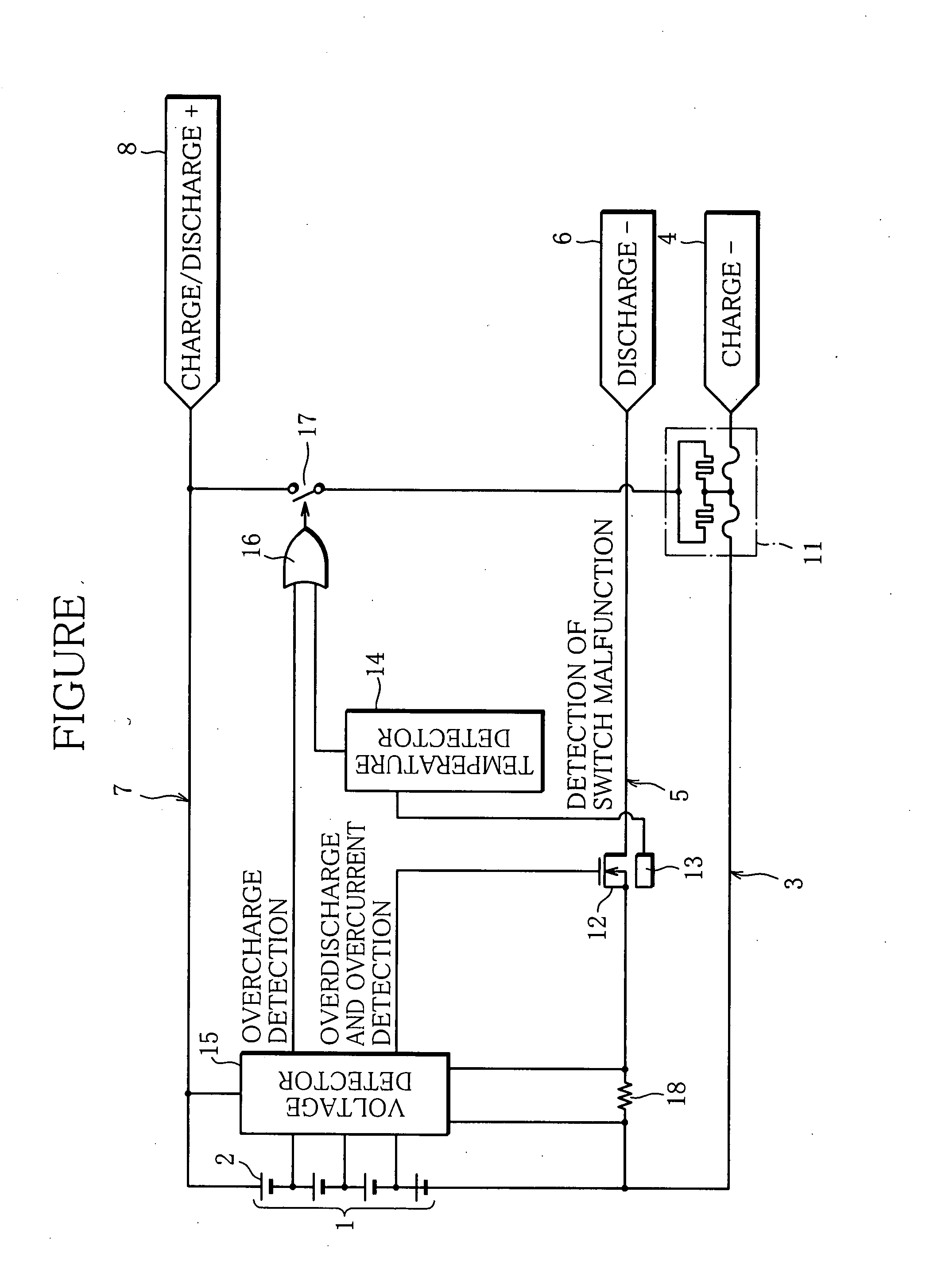
[0017] FIGURE shows a schematic configuration of the rechargeable battery device as described. Reference numeral 1 represents the rechargeable battery. The rechargeable battery 1 is constructed as battery group that maintains given cell voltage and capacity corr...


PUM


Abstract

Charging and discharging lines for a rechargeable battery are arranged independently from each other, and as a protection circuit for the rechargeable battery, there are provided a nonreturn-type switch (for example, thermo-fuse with an internal heater) that is interposed in the charging line in series and interrupts the charging line by blowout and a semiconductor switch (for example, MOS-FET) that is interposed in the discharging line in series and electrically continues or interrupts the discharging line. The switch control circuit turns off the semiconductor switch element when detecting overdischarge of the rechargeable battery, and blows out the nonreturn-type switch when detecting overcharge of the rechargeable battery or a malfunction of the semiconductor switch element.

Description

BACKGROUND OF THE INVENTION [0001] 1. Field of the Invention [0002] The present invention relates to a rechargeable battery device having an overcharge protection function and an overdischarge protection function for a rechargeable battery and having a simple structure in which safety is ensured. [0003] 2. Description of the Related Art [0004] A rechargeable battery, such as a Lithium-ion battery and a Nickel-Metalhalide battery, is deteriorated in battery characteristics by overcharge. Overdischarge of the rechargeable battery has the possibility of decreasing the safety of the battery. Likewise, if the discharge current of the rechargeable battery exceeds its rated value, the safety is possibly decreased by abnormal heat generation of the battery. [0005] Given these factors, for example, as disclosed in Unexamined Japanese Patent Publication No. 2001-126772, a semiconductor switch element (for example, MOS-FET) that electrically continues or interrupts a charging / discharging line ...

Claims


Application Information

Patent Timeline
IPC IPC(8): H02J7/00
CPCH02H3/023H01M10/44Y02E60/10
Inventor SEKI, MASAHIRO
Owner GK BRIDGE 1
Why Eureka
Try Eureka