
Systems and methods for suppressing feedback and reference noise in a phase lock loop circuit

a phase lock loop and reference noise technology, applied in the direction of electrical equipment, pulse automatic control, etc., can solve the problems of increasing space requirements, slow operation, and all of the problems, and achieve the effect of reducing any rippl

Active Publication Date: 2007-09-20
TEXAS INSTR INC
View PDF3 Cites 14 Cited by
  • Summary
  • Abstract
  • Description
  • Claims
  • Application Information

AI Technical Summary

Benefits of technology

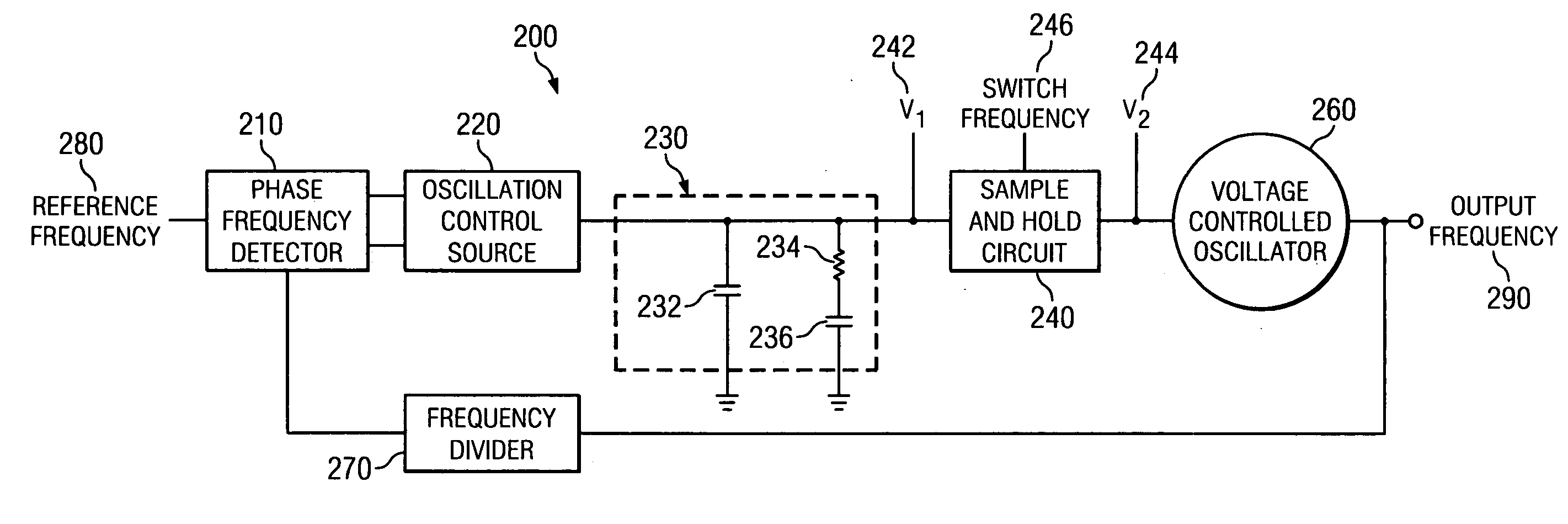
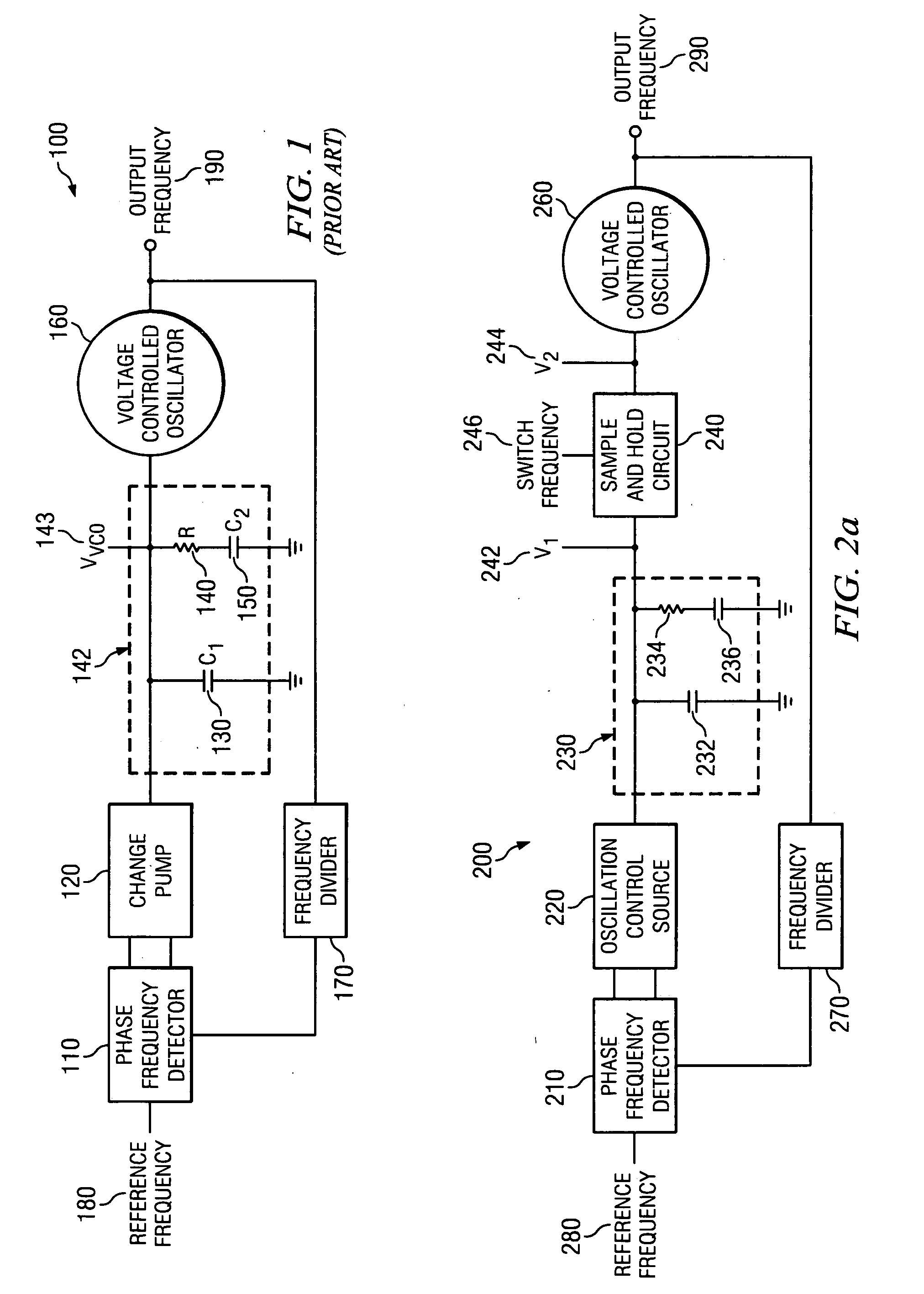
[0007]In some instances of the embodiments, the system further includes a divider circuit that is driven by the controllable oscillator. In addition, a phase / frequency detector is included that drives the oscillation control source, and is driven by a reference frequency and an output of the divider circuit. In addition, some instances of the embodiments include a filter disposed between the oscillation control source and the controllable oscillator. The filter may provide a stabilizing zero and a capacitor that is operable to reduce any ripple on the control input to the controllable oscillator.

Problems solved by technology

This, of course incurs all of the problems associated with using large capacitors including slow operation, and increased space requirements.

Method used


Image

  • Systems and methods for suppressing feedback and reference noise in a phase lock loop circuit
  • Systems and methods for suppressing feedback and reference noise in a phase lock loop circuit
  • Systems and methods for suppressing feedback and reference noise in a phase lock loop circuit

Examples


Embodiment Construction

[0020]The present invention is related to systems and methods for clock management, and in particular to systems and methods for maintaining a constant clock frequency.

[0021]Some embodiments of the present invention provide for systems for clock management. As used herein, the term “clock” is used in its broadest sense to mean any signal whether it be electrical, optical or otherwise that exhibits a particular frequency or range of frequencies. Thus, as just one of many examples, a clock may be a synchronizing signal used on a semiconductor device to control operation of one or more electrical circuits. Such a clock may be specified as, for example, a ten megahertz signal plus of minus ten percent. Based on the disclosure provided herein, one of ordinary skill in the art will recognize a myriad of clocks that may be used in accordance with embodiments of the present invention. Further, as used herein, the phrase “clock management” is used in its broadest sense to mean any activity w...


PUM


Abstract

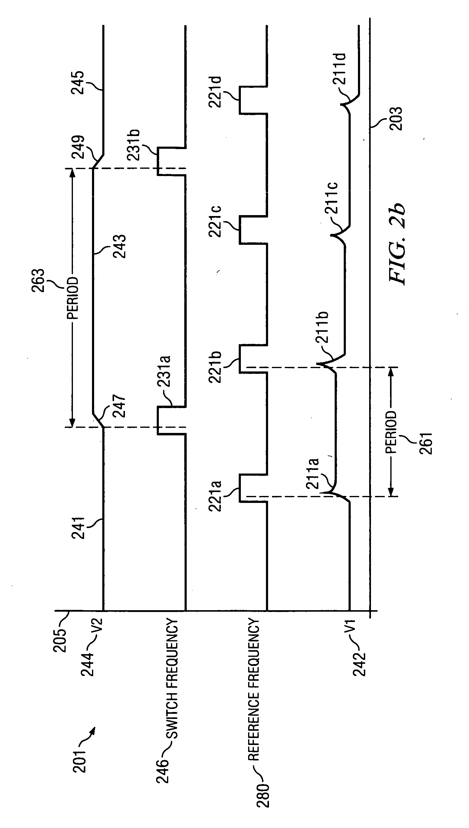
Various systems and methods for clock management. As one example, a system for clock management is disclosed that includes a controllable oscillator, an oscillation control source, and a sample and hold circuit. The sample and hold circuit is disposed between the oscillation control source and the controllable oscillator, and is operable to introduce a transfer function having a sin x / x characteristic with a null at a switch frequency applied to the sample and hold circuit.

Description

BACKGROUND OF THE INVENTION[0001]The present invention is related to systems and methods for clock management, and in particular to systems and methods for maintaining a desired clock frequency.[0002]Phase lock loop circuits are used in many applications as frequency synthesizers to generate a precise frequency signal with both good phase noise and low spurs. An exemplary basic phase lock loop circuit is shown in FIG. 1, and may be used to manage clock frequency and phase. Turning to FIG. 1, a basic phase lock loop circuit 100 is shown that includes a phase / frequency detector 110, a charge pump 120, a loop filter 142 consisting of two capacitors 130, 150 and a resistor 140, a voltage controlled oscillator 160, and a frequency divider 170. In operation, a reference frequency 180 is compared with a divided feedback of an output frequency 190, and the comparison is used to drive voltage controlled oscillator 160 to form output frequency 190 consistent with reference frequency 180. Wher...

Claims


Application Information

Patent Timeline
Patent Type & Authority Applications(United States)
IPC IPC(8): H03L7/00
CPCH03L7/14H03L7/093
Inventor KRISHNAN, KOUSHIKBATTACHARYA, PRASUN KALI
Owner TEXAS INSTR INC
Learn More