
Laser beam scanning apparatus, image forming apparatus, and laser beam scanning method

a laser beam and scanning apparatus technology, applied in the field of laser beam scanning apparatus, can solve the problems of increasing cost, affecting the quality of laser beam irradiation, and inconvenient machining of f- lenses, etc., and achieve the effect of high speed

Inactive Publication Date: 2007-09-20
KK TOSHIBA +1
View PDF4 Cites 13 Cited by
  • Summary
  • Abstract
  • Description
  • Claims
  • Application Information

AI Technical Summary

Benefits of technology

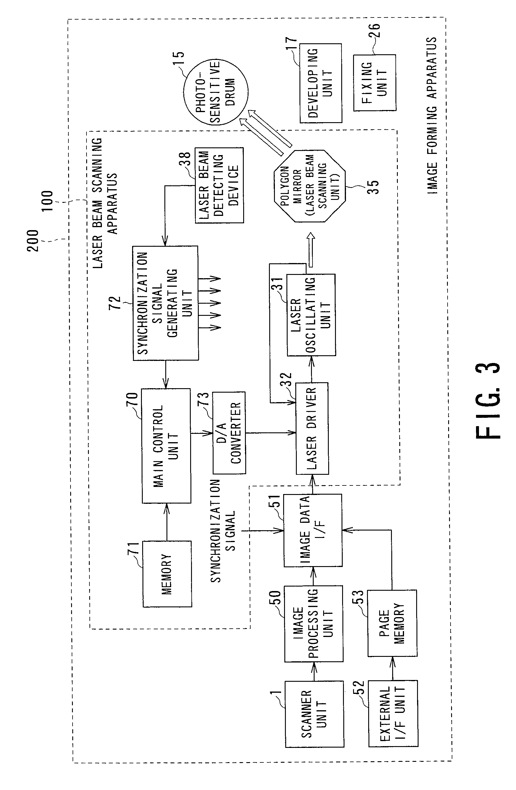
The invention is a laser beam scanning apparatus, image forming apparatus, and laser beam scanning method that can correct laser beam intensity in a main scanning direction on a photosensitive drum to be constant and perform electric correction at high speed. The apparatus includes an error signal generating unit that monitors laser beam intensity and generates an error signal, a correction signal generating unit that generates a correction signal to correct the intensity of the laser beam, a correction signal converting unit that converts the correction signal to an adapted correction signal, and a laser control signal generating unit that holds a reference signal and applies the adapted correction signal to the reference signal to generate a laser control signal for determining the intensity of the laser beam outputted from the laser oscillating unit. The technical effect of the invention is to provide a faster and more accurate way to control the intensity of the laser beam in the image forming process.

Problems solved by technology

However, even if an output of the laser oscillator is fixed, intensity of a laser beam irradiated on a photosensitive member (the photosensitive drum) is not always constant.
Consequently, machining of the f-θ lens takes time.
As a result, an increase in cost is caused.

Method used


Image

  • Laser beam scanning apparatus, image forming apparatus, and laser beam scanning method
  • Laser beam scanning apparatus, image forming apparatus, and laser beam scanning method
  • Laser beam scanning apparatus, image forming apparatus, and laser beam scanning method

Examples


first embodiment

(2) Correction in a Main Scanning Direction (First Embodiment)

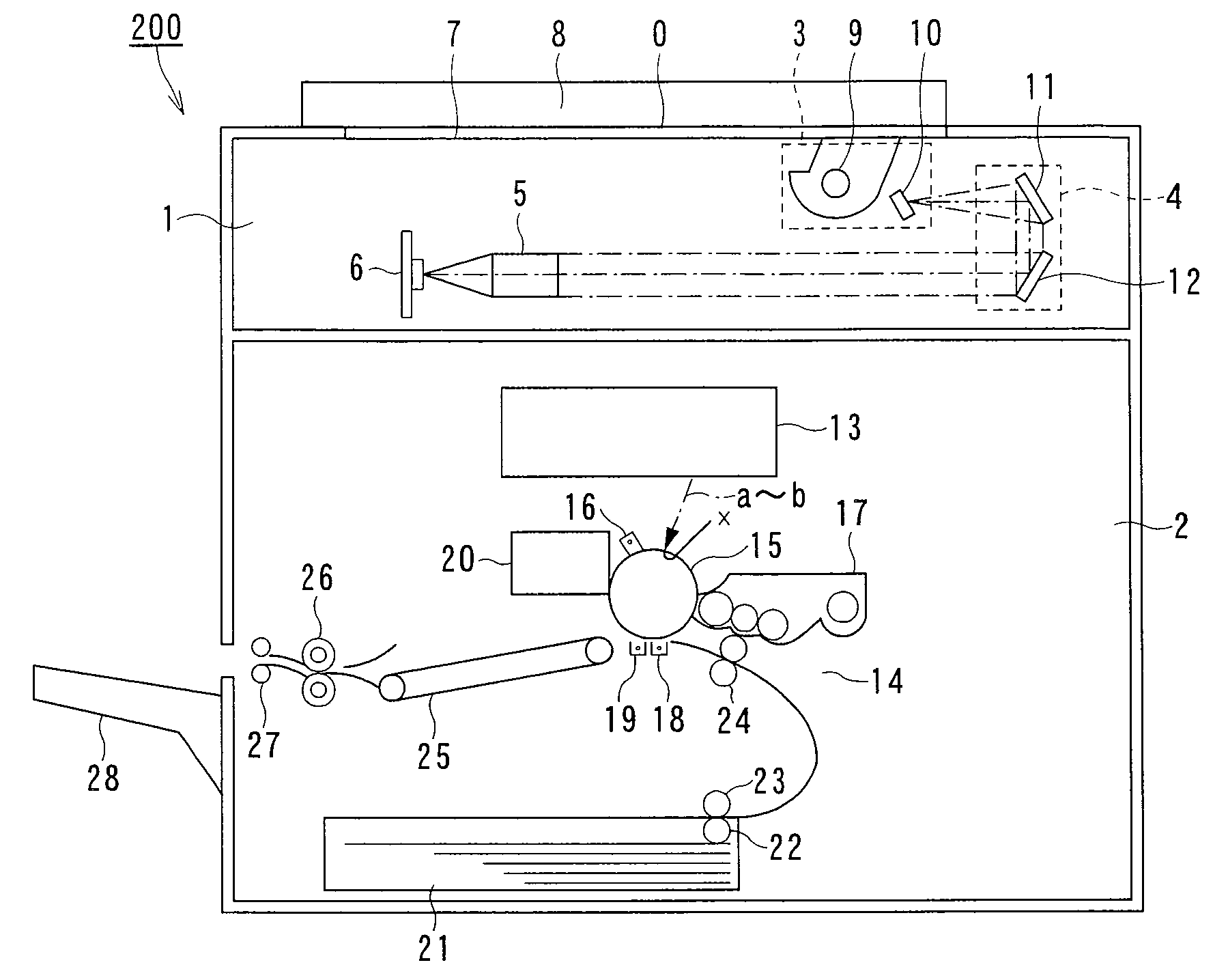
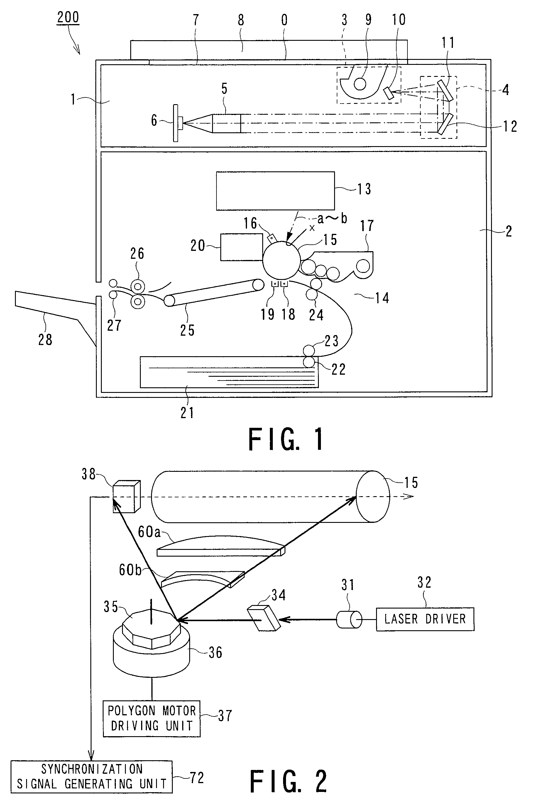
[0068]FIG. 4 is a diagram showing a path leading from the laser oscillating unit 31 to the photosensitive drum 15.

[0069] An angle of incidence of a beam to the main scanning direction of the f-θ lens is close to vertical near the center of the lens (a beam position B). The laser beam is made incident obliquely at a larger angle in positions closer to the ends of the lens (beam positions A and C). Therefore, a transmission loss of the lens with respect to the main scanning direction in one line increases from the center of the lens to the ends of the lens. As a result, even if a laser power output of a laser beam source is fixed, laser power on the surface of a photosensitive drum is large in the center and small at the ends.

[0070]FIGS. 5A to 5D are diagrams illustrating a situation in which laser power on the surface of the photosensitive drum is not uniform because of the reason described above.

[0071]FIG. 5A is a diag...


PUM


Abstract

A laser beam scanning apparatus includes: a laser oscillating unit that outputs a laser beam; a laser beam scanning unit that scans and irradiates the laser beam in a main scanning direction on a photosensitive member; an error signal generating unit that monitors intensity of a laser beam and generates an error signal between output intensity of the laser oscillating unit and a reference value; a correction signal generating unit that generates a correction signal for correcting intensity of a laser beam along the main scanning direction to be constant; a correction signal converting unit that converts a correction signal into an adapted correction signal by attenuating the correction signal; and a laser control signal generating unit that holds, during the image formation period, a reference signal generated on the basis of the error signal and applies the adapted correction signal to the reference signal to generate a laser control signal for determining intensity of a laser beam outputted from the laser oscillating unit.

Description

BACKGROUND OF THE INVENTION [0001] 1. Field of the Invention [0002] The present invention relates to a laser beam scanning apparatus, an image forming apparatus, and a laser beam scanning method, and, more particularly to a laser beam scanning apparatus that scans a photosensitive drum included in an image forming apparatus such as a laser printer or a digital copying machine with a laser beam to form an electrostatic latent image, an image forming apparatus having the laser beam scanning apparatus, and a laser beam scanning method. [0003] 2. Description of the Related Art [0004] In recent years, various image forming apparatuses such as a digital copying machine and a laser printer that perform image formation according to scanning exposure by a laser beam and an electrophotographic process have been developed. [0005] These image forming apparatuses include a laser beam scanning apparatus that scans a photosensitive drum with a laser beam to form an electrostatic latent image on th...

Claims


Application Information

Patent Timeline
Patent Type & Authority Applications(United States)
IPC IPC(8): B41J2/435
CPCG06K15/1219
Inventor KOMIYA, KENICHITANIMOTO, KOJIISHIKAWA, DAISUKEINAGAWA, YUJI
Owner KK TOSHIBA
Learn More