
Holographic memory medium, holographic memory device and holographic recording device

a technology of holographic memory and recording device, which is applied in the direction of recording/reproducing/erasing using optical interference patterns, data recording, instruments, etc., can solve the problems of inability to obtain an adequate reproduction signal, tilt error cannot be corrected by drive control of actuator for reference beam,

Inactive Publication Date: 2007-09-20
AKONIA HOLOGRAPHICS
View PDF6 Cites 17 Cited by
  • Summary
  • Abstract
  • Description
  • Claims
  • Application Information

AI Technical Summary

Benefits of technology

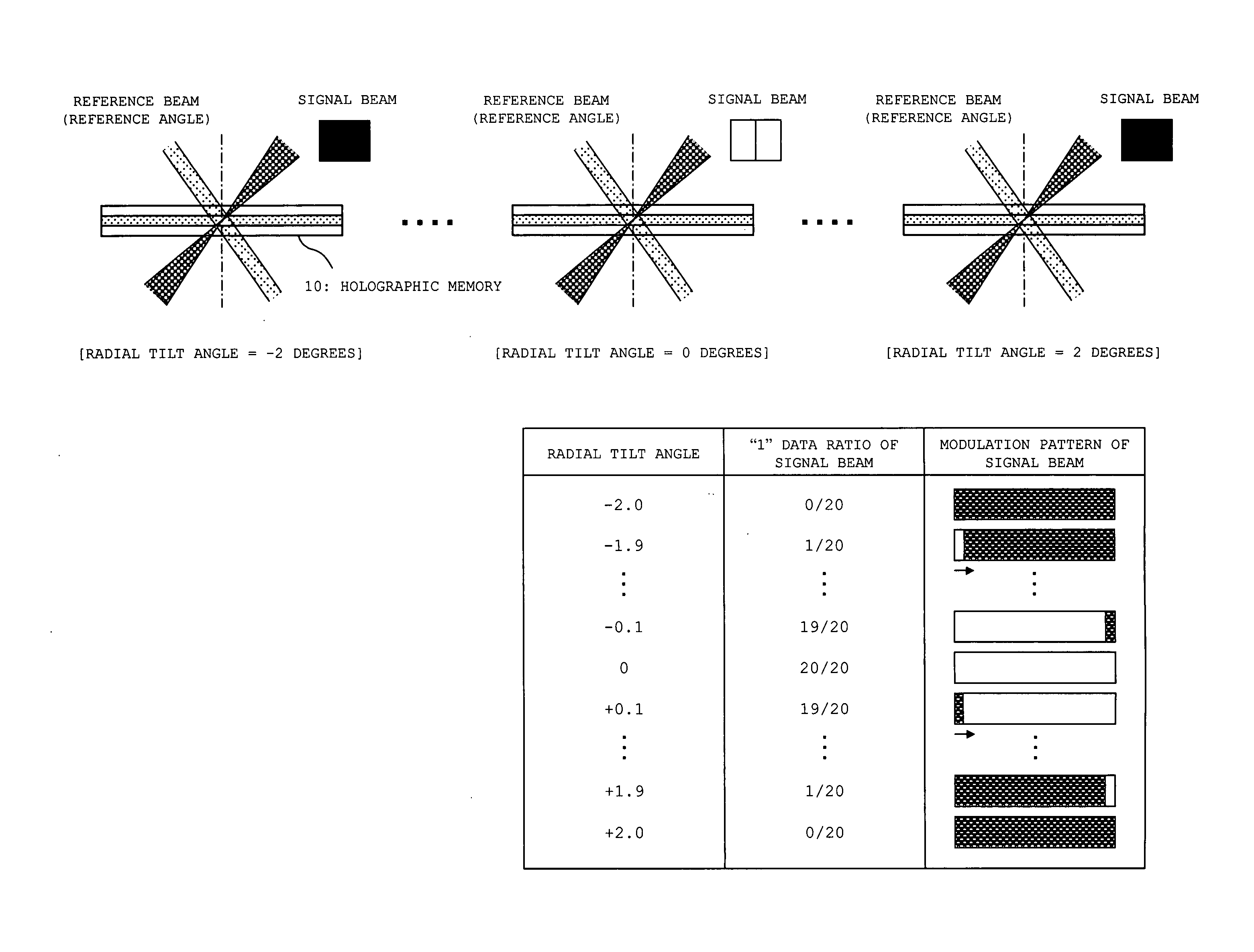
[0011] The present invention has been made to solve the above-mentioned problem. An object of the present invention is to be able to adequately record and reproduce information in and from a holographic memory by correction of a tilt error even when the tilt error is caused in the holographic memory in a direction perpendicular to a surface including optical axes of a signal beam and a reference beam.
[0027] According to the present invention, when the reference beam is emitted to the recording position of the reference information, it is possible to detect the incident angle of the reference beam which is specified by the reference information. Therefore, when the incident angle of the reference beam relative to the holographic memory medium or the incident angles of the reference beam and the signal beam relative thereto is / are adjusted based on the detected incident angle, the reference beam or the reference beam and the signal beam can be allowed to enter the holographic memory medium at adequate constant angle(s) during recording and reproducing operations.

Problems solved by technology

However, when the tilt error is caused in a direction perpendicular to the surface including the optical axes of the signal beam and the reference beam, that is, when the tile error is caused in an in-plane direction of the X-Z plane shown in FIGS. 12A and 12B, the tilt error cannot be corrected by drive control of the actuator for reference beam.
In such a case, an angle between the interference fringe and the reference beam is different from that at the time of recording, so it is impossible to obtain an adequate reproduction signal.

Method used


Image

  • Holographic memory medium, holographic memory device and holographic recording device
  • Holographic memory medium, holographic memory device and holographic recording device
  • Holographic memory medium, holographic memory device and holographic recording device

Examples


embodiment 1

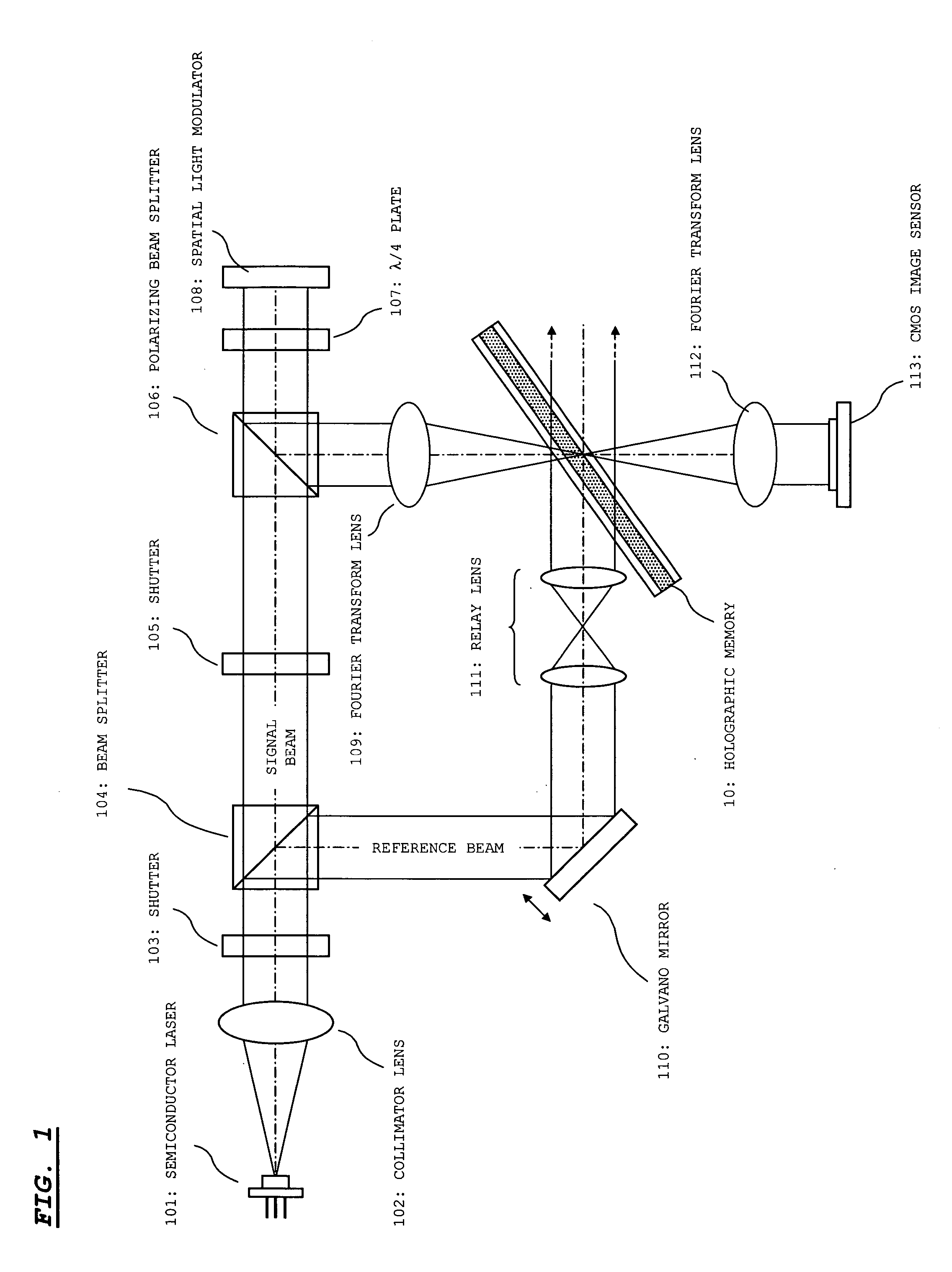
[0043]FIG. 1 shows an optical system of a holographic memory device according to this embodiment of the present invention. The shown optical system is used when information is recorded / reproduced in a transmissive holographic memory 10.

[0044] As shown in FIG. 1, this optical system includes a semiconductor laser 101, a collimator lens 102, a shutter 103, a beam splitter 104, a shutter 105, a polarizing beam splitter 106, a λ / 4 plate 107, a spatial light modulator 108, a Fourier transform lens 109, a galvano mirror 110, a relay lens 111, and a Fourier transform lens 112, and a CMOS (Complementary MOS) image sensor 113.

[0045] The semiconductor laser 101 emits a laser beam of a wavelength suited to the holographic memory 10. The collimator lens 102 converts the laser beam made incident from the semiconductor laser 101 into a parallel beam. The shutter 103 includes a mechanical shutter or the like, and passes / blocks a laser beam according to a control signal. Specifically, an OFF (pas...

embodiment 2

[0097] In Embodiment 1, the incident angle of the reference beam in the tangential tilt direction is maintained to the reference angle St to form the reference tilt hologram. Then, the total received light quantity is detected for each incident angle while the incident angle of the reference beam in the tangential tilt direction is changed relative to the reference tilt hologram. An incident angle associated with a largest total received light quantity is obtained as the reference angle St in the tangential tilt direction.

[0098] On the other hand, in this embodiment, a reference tilt hologram for obtaining the reference angle St (hereinafter referred to as a “Tn-reference tilt hologram”) is formed in the holographic memory in addition to the reference tilt hologram described in Embodiment 1 (hereinafter referred to as particularly a “Ra-reference tilt hologram” in this embodiment).

[0099] As in the case of the Ra-reference tilt hologram, it is preferable to form the Tn-reference ti...

embodiment 3

[0115] In Embodiment 2, each of the reference angles St and Sr is obtained by the method shown in FIG. 5. On the other hand, in Embodiment 3, each of the reference angles St and Sr is obtained with reference to the total received light quantities obtained while the reference beam is changed in the tangential tilt direction and the radial tilt direction.

[0116] In this embodiment, in forming the reference tilt hologram, the incident angle of the reference beam is maintained to a reference angle without being changed in the tangential tilt direction and in the radial tilt direction. The reference beam is allowed to enter at the reference angle to record only one kind of signal pattern (any pattern is allowed). Therefore, the reference tilt hologram is formed in the holographic memory 10.

[0117]FIG. 10 is a processing flow chart showing processing for obtaining and setting the reference angles St and Sr. This processing is performed before the recording and reproducing operations.

[011...


PUM


Abstract

Even when a tilt error is caused in a holographic memory in a direction perpendicular to a surface including optical axes of a signal beam and a reference beam (radial tilt direction), the signal beam and the reference beam are allowed to enter the holographic memory at adequate angles relative thereto at all times by suppression of the tilt error. A reference tilt hologram for specifying a reference incident angle of the reference beam in a radial tilt direction is recorded in advance on a holographic memory medium. During recording and reproducing operations, the reference beam is emitted to a recording position of the reference tilt hologram and the reference incident angle (reference angle Sr) of the reference beam in the radial tilt direction is detected based on a received light state. A tilt actuator (19) for displacing the holographic memory medium in the radial tilt direction is driven to adjust an incident angle of the reference beam in the radial tilt direction to the reference angle Sr. Then, the signal beam and the reference beam are emitted to the holographic memory medium to execute the recording and reproducing operations.

Description

BACKGROUND OF THE INVENTION [0001] 1. Field of the Invention [0002] The present invention relates to a holographic memory medium on which information is recorded by fixing interference fringes generated when a signal beam interferes with a reference beam therein, a holographic memory device for recording and reproducing the information in and from the holographic memory medium, and a holographic recording device for recording the information in the holographic memory medium. In particular, the present invention is suitable to correct a tilt error caused between the holographic memory medium and the reference beam. [0003] 2. Description of the Related Art [0004] Generally, in the holographic memory, information is recorded by fixing an interference fringe, which is generated by an interference caused therein between a signal beam and a reference beam, in a holographic memory material layer. In this case, the signal beam is subjected to spatial light modulation according to the inform...

Claims


Application Information

Patent Timeline
IPC IPC(8): G03H1/28
CPCG03H2001/0473G11B7/0956G11B7/00772G11B7/0065
Inventor MATSUMURA, YOSHIYUKIREDMOND, IAN RUSSELLMALANG, KEITH
Owner AKONIA HOLOGRAPHICS
Learn More