Reflective illumination device
- Summary
- Abstract
- Description
- Claims
- Application Information
AI Technical Summary
Benefits of technology
Problems solved by technology
Method used
Image
Examples
first embodiment
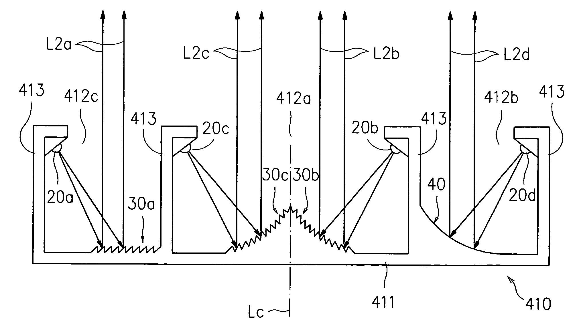
[0049] Please refer to FIG. 5, which is a schematic diagram illustrating a reflective illumination device according to the invention. The illumination device of FIG. 5 is comprised of a light-guiding screen 10, made of a material of light reflecting ability, and at least a light source 20; wherein a light reflecting layer is disposed at the inner wall of the light-guiding screen 10 for increasing the reflectance of the light-guiding screen 10. The light reflecting layer can be a reflective diffusion film, commonly seen in conventional flat panel display, or can be formed by electro-depositing a layer of metal, such as aluminum or electroless nickel, etc. Each light source 20 can be a directional light source capable of emitting light beams by a specific angle, such as light emitting diode (LED). Moreover, the light-guiding screen 10 has a bottom 11 and at least a light-discharging exit 12 formed by the enclosure of a side wall. As seen in FIG. 5, the illumination device is character...
third embodiment
[0054] Please refer to FIG. 7, which a schematic diagram illustrating a reflective illumination device according to the invention. In FIG. 7, the light-guiding screen 210, having a bottom 211 and a light-discharging exit 212, in which the two semi-Fresnel lens structures 30b, 30c and their corresponding light sources 20b, 20c are symmetrically arranged with respect to an axis Lc. The difference between the reflective illumination device of FIG. 7 and that of FIG. 6 is that the two semi-Fresnel lens structures 30b, 30c are respectively arranged on two curved surfaces 214, 215, while the two semi-Fresnel lens structures 30b, 30c are respectively configured with a plurality of ridges 31b, 31c. For matching to the ridges 31b, 31c in respective, the light source 20b, 20c are respectively inclined by an angle θb, θc and disposed at the upper fringe of side wall 213 enclosing the light-discharging exit 212 for enabling the light beams L1b, L1c of the light source to be emitted by a specifi...
PUM
 Abstract
Description
Claims
Application Information
 - R&D
- Intellectual Property
- Life Sciences
- Materials
- Tech Scout
- Unparalleled Data Quality
- Higher Quality Content
- 60% Fewer Hallucinations
Browse by: Latest US Patents, China's latest patents, Technical Efficacy Thesaurus, Application Domain, Technology Topic, Popular Technical Reports.
© 2025 PatSnap. All rights reserved.Legal|Privacy policy|Modern Slavery Act Transparency Statement|Sitemap|About US| Contact US: help@patsnap.com


