Imaging apparatus

Inactive Publication Date: 2007-09-20
RICOH KK
View PDF6 Cites 10 Cited by
  • Summary
  • Abstract
  • Description
  • Claims
  • Application Information

AI Technical Summary

Benefits of technology

[0020] According to an aspect of the present invention, a technique is provided for accurately reducing positio

Problems solved by technology

The variable component occurring over the rotation period of the photoconductor drum may be primarily caused by transmission errors of a drive transmission system arranged at the photoconductor drum shaft (e.g., transmission errors caused by gear eccentricity and/or gear cumulative pitch deviation) or transmission errors of a coupling element that detachably couples the photoconductor drum to the drive transmission system (e.g., transmission errors caused by shaft tilting and/or shaft center deviation), for example.
In a tandem imaging apparatus, there may be variations in the amplitudes and phases of the positional deviation variable components (i.e., deviation from the desired transfer position) of the image forming units over a predetermined section of the transfer belt (i.e., transfer area covered by one rotation of each photoconductor drum), and such variations may lead to image quality degradation.
Further, when the phase of the rotational speed variation differs for each photoconductor drum of each color, variations are created in the amount of positional deviations of the different colors to thereby result in color drift.
However, with respect to the eccentricity component attributed to the coupling element, since positional deviations of the coupling elements are caused by rotation of the coupling elements upon attaching/detaching the

Method used


Image

  • Imaging apparatus
  • Imaging apparatus
  • Imaging apparatus

Examples


Embodiment Construction

[0069] In the following, preferred embodiments of the present invention are described with reference to the accompanying drawings. It is noted that although a tandem printer that uses the intermediate transfer (indirect transfer) scheme is described below as an illustrative embodiment, the present invention is not limited to such an embodiment and may equally be applied to other types of imaging apparatuses. Also, it is noted that in the following descriptions the terms “image carrier” and “photoconductor drum” are used interchangeably.

[0070] (Overall Apparatus Configuration)

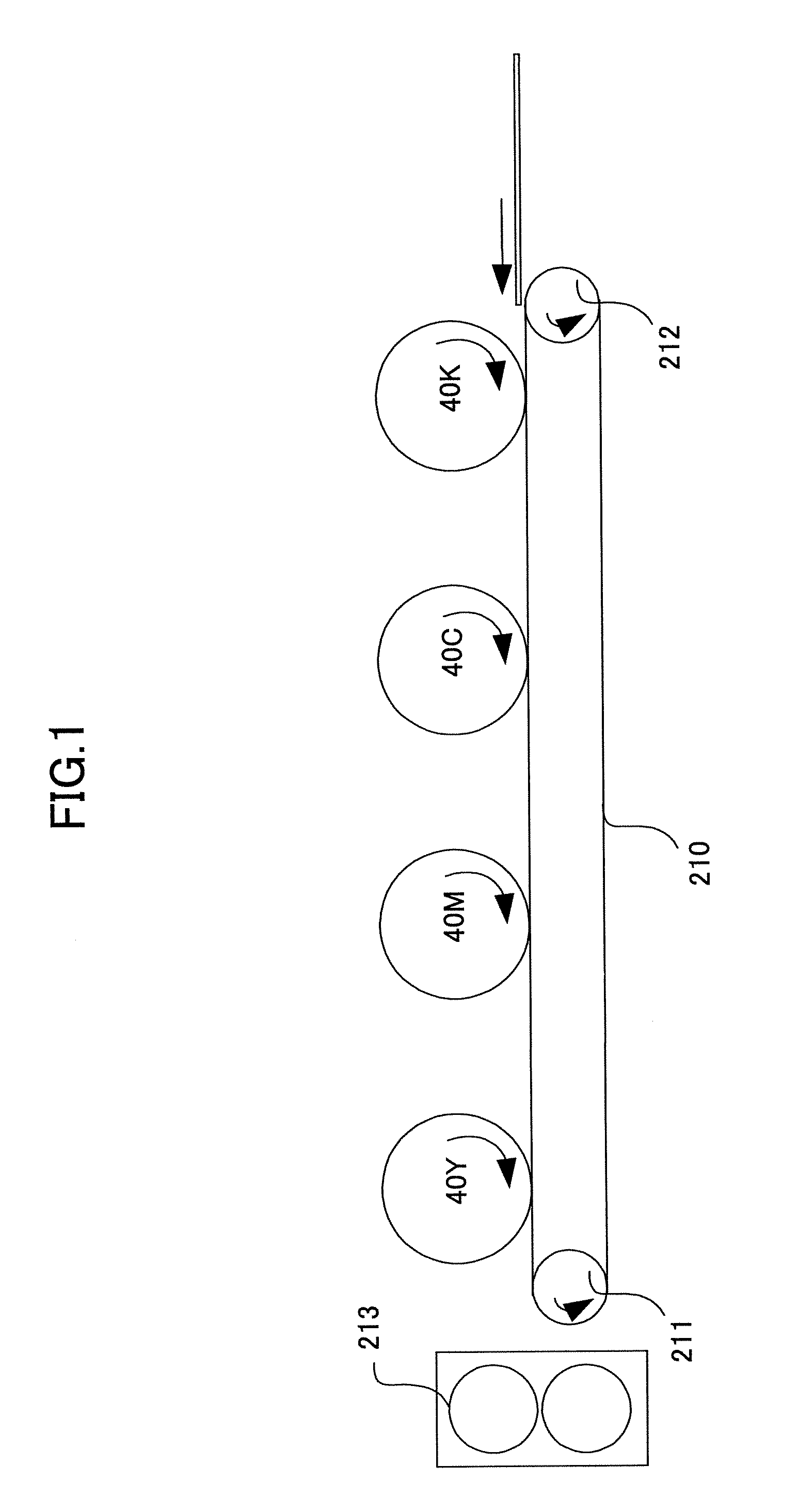
[0071]FIG. 3 is a diagram showing a basic configuration of a printer as an imaging apparatus according to an embodiment of the present invention.

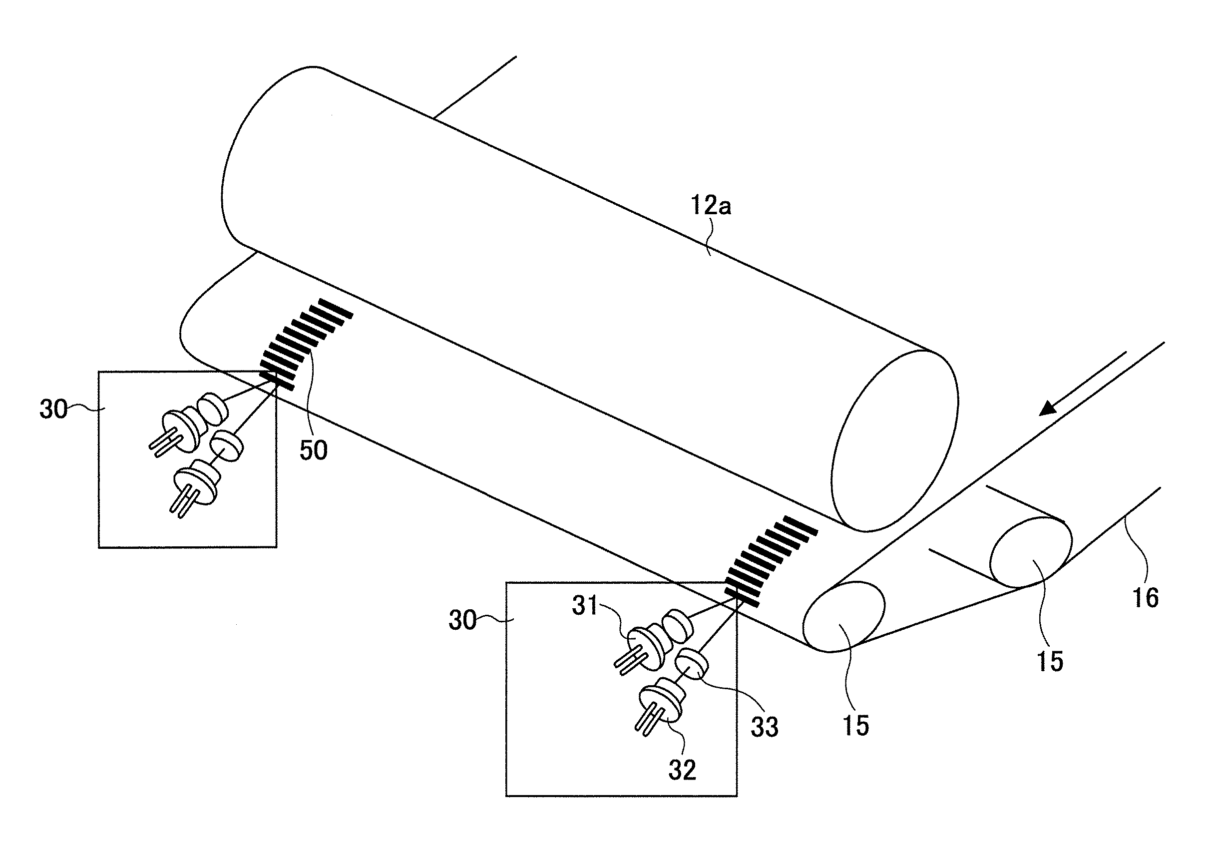
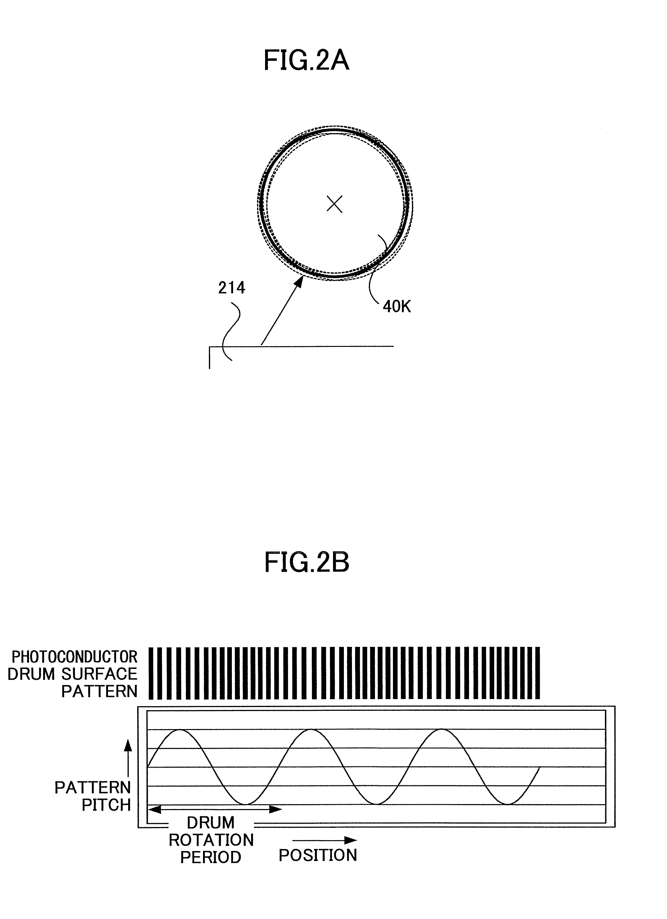
[0072] The illustrated printer 1 includes an exposure unit 11, a black image carrier 12a, a cyan image carrier 12b, a magenta image carrier 12c, a yellow image carrier 12d, bias rollers 13a, 13b, 13c, 13d, a drive roller 14, support rollers 15, an intermediate transf...


PUM


Abstract

An imaging apparatus is disclosed that includes plural image carriers on which different-colored toner images are formed, the image carriers being driven and rotated to transfer the different-colored toner images onto one of an endless transfer member that is driven to rotate in contact with the image carriers or a transfer material that is carried by the endless transfer member. The imaging apparatus includes a phase calculating unit that extracts a periodic rotational variation component of each of the image carriers from a combination of periodic rotational variation components generated within said imaging apparatus and calculates a rotational phase of each of the image carriers based on the extracted periodic rotational variation component, and a rotational phase adjusting unit that adjusts a rotation stop phase of each of the image carriers based on the calculated rotational phase.

Description

BACKGROUND OF THE INVENTION [0001] 1. Field of the Invention [0002] The present invention relates to an imaging apparatus. [0003] 2. Description of the Related Art [0004] With recent advancements in the quality and speed of administrative paperwork at the office, for example, there is a growing demand for a color imaging apparatus such as a copier, a printer, or a facsimile machine with higher image quality and higher processing speed. A tandem color imaging apparatus is one type of imaging apparatus that is being developed in view of such a demand. For example, the tandem color imaging apparatus may include image forming units for the colors black (K), yellow (Y), magenta (M), and cyan (C), and may be configured to form a color image by transferring the different color images created by the image forming units in an overlapping manner onto a transfer material or an intermediate transfer medium that moves across the image forming units. It is noted that various types of the tandem c...

Claims


Application Information

Patent Timeline
IPC IPC(8): G03G15/01
CPCG03G15/5008G03G15/0194G03G2215/0161
Inventor MATSUDA, YUJIEHARA, YASUHISAKOBAYASHI, KAZUHIKOEBARA, JOHFUNAMOTO, NORIAKIHANDA, SEIICHIMATSUDA, HIROMICHI
Owner RICOH KK
Why Eureka
Try Eureka