CMP pad conditioner

a polishing pad and conditioner technology, applied in the direction of grinding drives, grinding surface conditioning devices, manufacturing tools, etc., can solve the problems of preventing stable and high grindability, inability to hold abrasive grains, etc., and achieve the effect of grinding a polishing pad stably and flatly

Inactive Publication Date: 2007-09-20
NORITAKE CO LTD +1
View PDF6 Cites 1 Cited by
  • Summary
  • Abstract
  • Description
  • Claims
  • Application Information

AI Technical Summary

Benefits of technology

[0022] Since abrasive grains having regular shapes are fixed to the flat part, the polishing pad can be ground flatly. At the same time, since abrasive grains having acute shapes are fixed to the inclined part, the polishing pad can be ground stably. Thus, flatness and stability in the grinding are satisfied simultaneously.
[0023] Further, if the abrasive grains of acute shape were fixed by electrodeposition, the abrasive grains would merely be caulked mechanically by plating. Thus, problems arise as follows. That is, since the abrasive grains have distorted shapes, the abrasive grains cannot be held unless the plating has a sufficient thickness. On the contrary, in the case of an excessive thickness, this prevents stable and high grindability that could be achieved by the abrasive grains of acute shape. In contrast, when the abrasive grains are fixed by soldering, the abrasive grains can be held firmly even with a solder of small thickness. This allows the abrasive grains of acute shape to act effectively.
[0027] When appropriate variation is imparted to the tip height values of the abrasive grains, flatness in the processing is achieved in a state that a grinding effect is maintained to some extent.
[0029] According to the present invention, a CMP pad conditioner is realized that can grind a polishing pad stably and flatly.

Problems solved by technology

Thus, problems arise as follows.
That is, since the abrasive grains have distorted shapes, the abrasive grains cannot be held unless the plating has a sufficient thickness.
On the contrary, in the case of an excessive thickness, this prevents stable and high grindability that could be achieved by the abrasive grains of acute shape.

Method used


Image

  • CMP pad conditioner
  • CMP pad conditioner

Examples


Embodiment Construction

[0032] The present invention is described below with reference to an embodiment.

[0033] A CMP pad conditioner of the present invention is described below with reference to an embodiment.

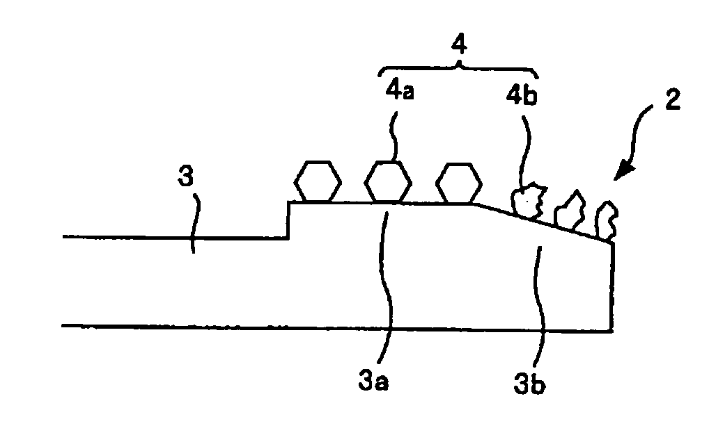
[0034]FIG. 1 shows a configuration of a CMP pad conditioner according to an embodiment of the present invention. FIG. 1(a) shows a conditioning disk of the CMP pad conditioner, where a grinding part 2 is provided on an outer periphery side of a conditioning disk 1.

[0035]FIG. 1(b) shows details of the grinding part 2. The grinding part 2 is formed in such a manner that abrasive grains 4 are fixed by soldering with a solder material such as Ni—Cr onto a metal base 3 composed of a metallic material such as steel and copper alloy. The abrasive grains 4 may be composed of diamond or the like. The metal base 3 includes a flat part 3a near the inner periphery and an inclined part 3b near the outer periphery. Abrasive grains 4a having regular shapes are fixed to the flat part 3a, while abrasive grains 4b h...


PUM


Abstract

A CMP pad conditioner is provided with a grinding part formed by fixing abrasive grains on a metal base by soldering, wherein the grinding part has a flat part near an inner periphery and an inclined part near an outer periphery, wherein abrasive grains having regular shapes are fixed to the flat part, and wherein abrasive grains having acute shapes are fixed to the inclined part.

Description

[0001] The present application claims the benefits of Japanese Patent Application No. 2006068855 filed on Mar. 14, 2006. BACKGROUND OF THE INVENTION [0002] 1. Field of the Invention [0003] The present invention relates to a CMP pad conditioner used in a CMP device used for flattening a surface of a silicon wafer or the like. [0004] 2. Description of the Related Art [0005] As a method of flattening a surface of a silicon wafer or the like, chemical mechanical polishing (abbreviated as “CMP,” hereinafter) has been used often in recent years. [0006]FIG. 2 shows a configuration of a CMP device used conventionally. [0007] In FIG. 2, a CMP device 51 includes a polishing head 54 and a conditioner 55 provided on a revolving table 53 that revolves about a revolving table shaft 52. A polishing pad 56 is formed on the upper surface of the revolving table 53. [0008] The polishing head 54 includes a polishing head shaft 57 and a disk-shaped wafer carrier 58. A wafer 59 is suctioned onto a lower ...

Claims


Application Information

Patent Timeline
Patent Type & Authority Applications(United States)
IPC IPC(8): B24B21/18B24B33/00B24B53/017B24B53/02B24B53/12B24D3/00
CPCB24B53/02B24B53/017
Inventor NONOSHITA, TETSUYATOGE, NAOKI
Owner NORITAKE CO LTD
Why Eureka
Try Eureka