Resolver signal processing device

a signal processing and signal technology, applied in the field of resolution signal processing devices, can solve the problems of increasing the total cost and imposing a significant achieve the effects of short time, and reducing the burden on the control portion

Active Publication Date: 2007-09-20
OMRON AUTOMOTIVE ELECTRONICS CO LTD
View PDF2 Cites 11 Cited by
  • Summary
  • Abstract
  • Description
  • Claims
  • Application Information

AI Technical Summary

Benefits of technology

[0009]The present invention aims at providing a resolver signal processing device capable of reducing a burden imposed on a control portion in applying an excitation signal to a resolver and simplifying processing steps, thereby contributing to increase in speed and cost.
[0013]According to the aforementioned structure, the excitation signal is output to the resolver by DMA transfer. Accordingly, such a processing requires an extremely shorter time, thereby reducing the burden on the calculation portion.
[0015]Also in detecting the rotational angle by transmitting to the resolver an excitation signal which has been compensated for the phase difference, by use of DMA transfer, the processing requires an extremely short time, thereby reducing the burden on the control portion.
[0016]According to the present invention, it is possible to reduce the burden on the control portion in applying the excitation signal to the resolver and to enable transmission of the excitation signal to the resolver only by commanding DMA transfer, which can simplify processing steps, thereby contributing to increase in speed and cost reduction.

Problems solved by technology

However, in detecting the rotational angle, the resolver signal processing device reads data by incrementing one by one the read address of the sine-wave ROM, which imposes a significant burden on a control portion.
This disturbs executing other processing or requires use of a device with a higher processing capacity, thereby inducing a problem of increase in a total cost.

Method used


Image

  • Resolver signal processing device
  • Resolver signal processing device
  • Resolver signal processing device

Examples


Embodiment Construction

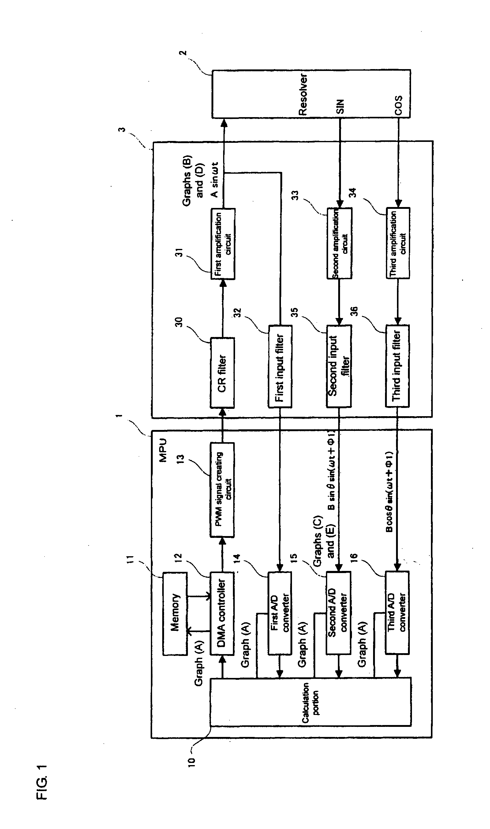
[0022]FIG. 1 shows a main-part block diagram of an EPS-ECU (electric power steering electronic control unit) according to an embodiment of the present invention.

[0023]The EPS-ECU is used for realizing a resolver signal processing function for controlling a resolver 2 coupled to a handle shaft in a vehicle and other functions for electric power steering control. This device includes a control portion (MPU) 1 which executes resolver signal processing and other processing, and an input / output portion 3 connected between the control portion 1 and the resolver 2.

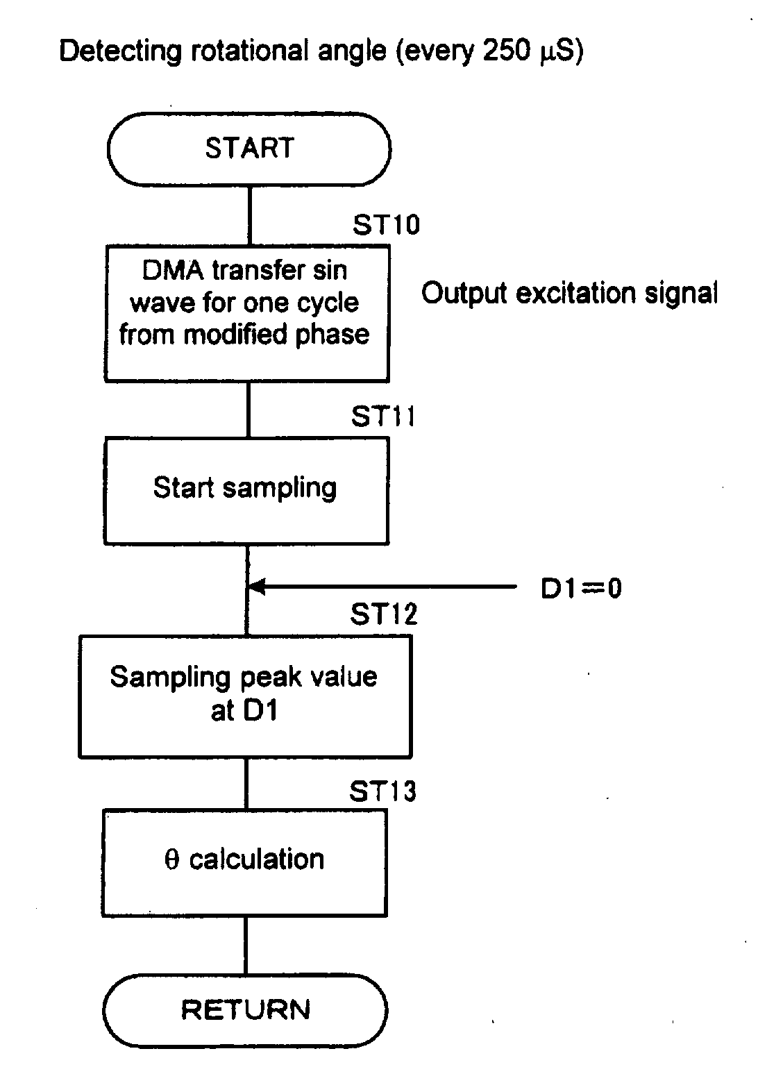
[0024]The control portion 1 includes a calculation portion 10, and a memory (storage portion) 11 which stores sine wave data for two cycles. The sine wave data stored in the memory 11 is duty ratio data with a value varying depending on the waveform level. The control portion 1 further includes a DMA controller 12 (DMA transfer portion) which performs control for DMA transfer of the sine wave data stored in the memory 11 for one ...


PUM

PropertyMeasurementUnit
rotational angleaaaaaaaaaa
phaseaaaaaaaaaa
phase differenceaaaaaaaaaa

Abstract

A resolver signal processing device includes a control portion, a resolver, and an input / output portion. The control portion includes a memory for storing sine wave data for two cycles, and a DMA controller for transmitting to the resolver the excitation signal including a sine wave. A calculation portion provided in the control portion commands, in initial setting, DMA transfer of the sine wave data for one cycle from a reference phase as the excitation signal, and commands, in detecting the rotational angle, DMA transfer of the sine wave data for one cycle from a modified phase as the excitation signal. The modified phase is determined, in the initial setting, based on the phase difference between the excitation signal and a sine wave output signal or a cosine wave output signal, and the rotational angle of the resolver.

Description

BACKGROUND OF THE INVENTION[0001]1. Field of the Invention[0002]The present invention relates to a resolver signal processing device for use in an EPS-ECU (Electronic Control Unit for Electric Power Steering) and the like.[0003]2. Description of the Related Art[0004]A resolver signal processing device is provided in an EPS-ECU, which is an in-vehicle electronic device, and detects a rotational angle θ of a handle shaft based on a signal from a resolver coupled to the handle shaft.[0005]A resolver induces a phase difference specific to the resolver, between an excitation signal applied to the resolver and resolver output signals (a sine wave output signal and a cosine wave output signal), which necessitates detecting, in advance, the phase difference for detecting the rotational angle θ and canceling a value of the phase difference in detecting the rotational angle.[0006]In initial setting at a predetermined timing such as at power-on of the resolver signal processing device and the ...

Claims


Application Information

Patent Timeline
Patent Type & Authority Applications(United States)
IPC IPC(8): G06F19/00G06F17/40G01D5/20G01D5/245
CPCG01D5/2046G01D5/2073G01D5/24457B23B39/04B23B43/00B23H7/02
Inventor KAWAGUCHI
Owner OMRON AUTOMOTIVE ELECTRONICS CO LTD
Why Eureka
Try Eureka