Common Rail Injector

a common rail and injector technology, applied in the direction of fluid pressure injection control, fuel injection apparatus, charge feed system, etc., can solve the problems of tolerance-sensitive and expensive, and achieve the effect of improving the tolerance performance of the injector, improving the efficiency of the injector, and fast switching speed of the valv

Inactive Publication Date: 2007-09-27
ROBERT BOSCH GMBH
View PDF10 Cites 6 Cited by
  • Summary
  • Abstract
  • Description
  • Claims
  • Application Information

AI Technical Summary

Benefits of technology

[0004] In a common rail injector for injecting fuel into a combustion chamber of an internal combustion engine, having an injector housing, which has a fuel supply line which communicates with a central high-pressure fuel source outside the injector housing and with a pressure chamber inside the injector housing, from which pressure chamber, as a function of the position of a control valve, especially a 3 / 2-way valve, fuel subjected to high pressure is injected, this object is attained in that the control valve, in particular the 3 / 2-way valve, includes a valve piston, movable back and forth in the injector housing between a position of repose and an injection position, which piston is coupled hydraulically with a piezoelectric actuator that is subjected to the pressure from the high-pressure fuel source. The piezoelectric actuator is subjected to pressure both axially and radially, or in other words transversely. The piezoelectric actuator serves to actuate the valve piston. With the omission of the control quantity that occurs in servo valves, the efficiency of the injector is improved. The requisite axial prestressing force for the piezoelectric actuator is generated hydraulically, at least in part. As a result, no major spring forces have to be implemented in the injector, which has advantages in terms of installation space and expense. Because of the very fast switching speed of the valve with a piezoelectric actuator, the tolerance performance of the injector can be improved. Moreover, the minimal-quantity capability (preinjection quantities) is assured.
[0005] A preferred exemplary embodiment of the common rail injector is characterized in that the injector housing includes a hydraulic coupling chamber, subjected to the pressure from the high-pressure fuel reservoir, by way of which coupling chamber the piezoelectric actuator is coupled hydraulically with the valve piston. A substantially circular-cylindrical head of metal can for instance be mounted on the piezoelectric actuator and its end face defines the hydraulic coupling chamber. On the diametrically opposite side, the hydraulic coupling chamber is preferably defined by a face end of the valve piston. The hydraulic coupling chamber serves to compensate for expansions in volume of the piezoelectric actuator that are caused by temperature fluctuations in operation. In addition, a force / travel boost can be implemented as a result between the piezoelectric actuator and the valve piston.
[0006] A further preferred exemplary embodiment of the common rail injector is characterized in that a first end of the valve piston defines the hydraulic coupling chamber, and a second end of the valve piston protrudes into a valve control chamber, which in the injection position of the valve piston is in communication with a fuel return and which in the position of repose of the valve piston is subjected to the pressure from the high-pressure fuel reservoir. The fuel return can communicate for instance with a fuel tank and makes a fast pressure reduction in the valve control chamber possible. In the position of repose of the valve piston, the injector is filled with fuel, at least partly, via the valve control chamber.
[0010] A further preferred exemplary embodiment of the common rail injector is characterized in that the valve piston is embodied in one piece. The one-piece version has the advantage that both sealing edges can be guided by the valve piston guide portion.
[0011] A further preferred exemplary embodiment of the common rail injector is characterized in that the valve piston is embodied in multiple parts, in particular in two parts. The multi-part version offers advantages in terms of production, especially in conjunction with a multi-part valve body.

Problems solved by technology

The control of known common rail injectors is usually done with servo valves or solenoids, which are expensive and tolerance-sensitive.

Method used


Image

  • Common Rail Injector
  • Common Rail Injector
  • Common Rail Injector

Examples


Embodiment Construction

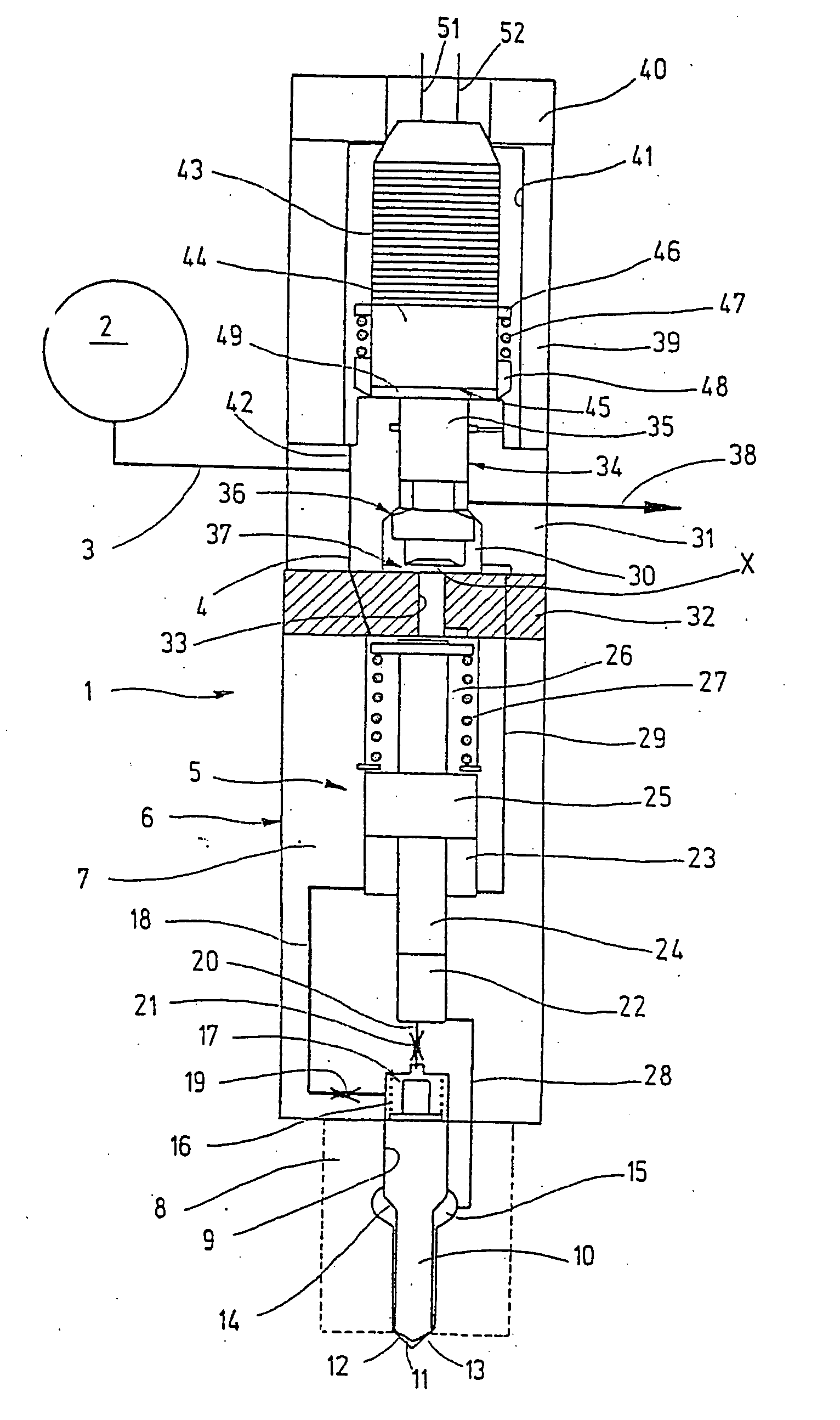
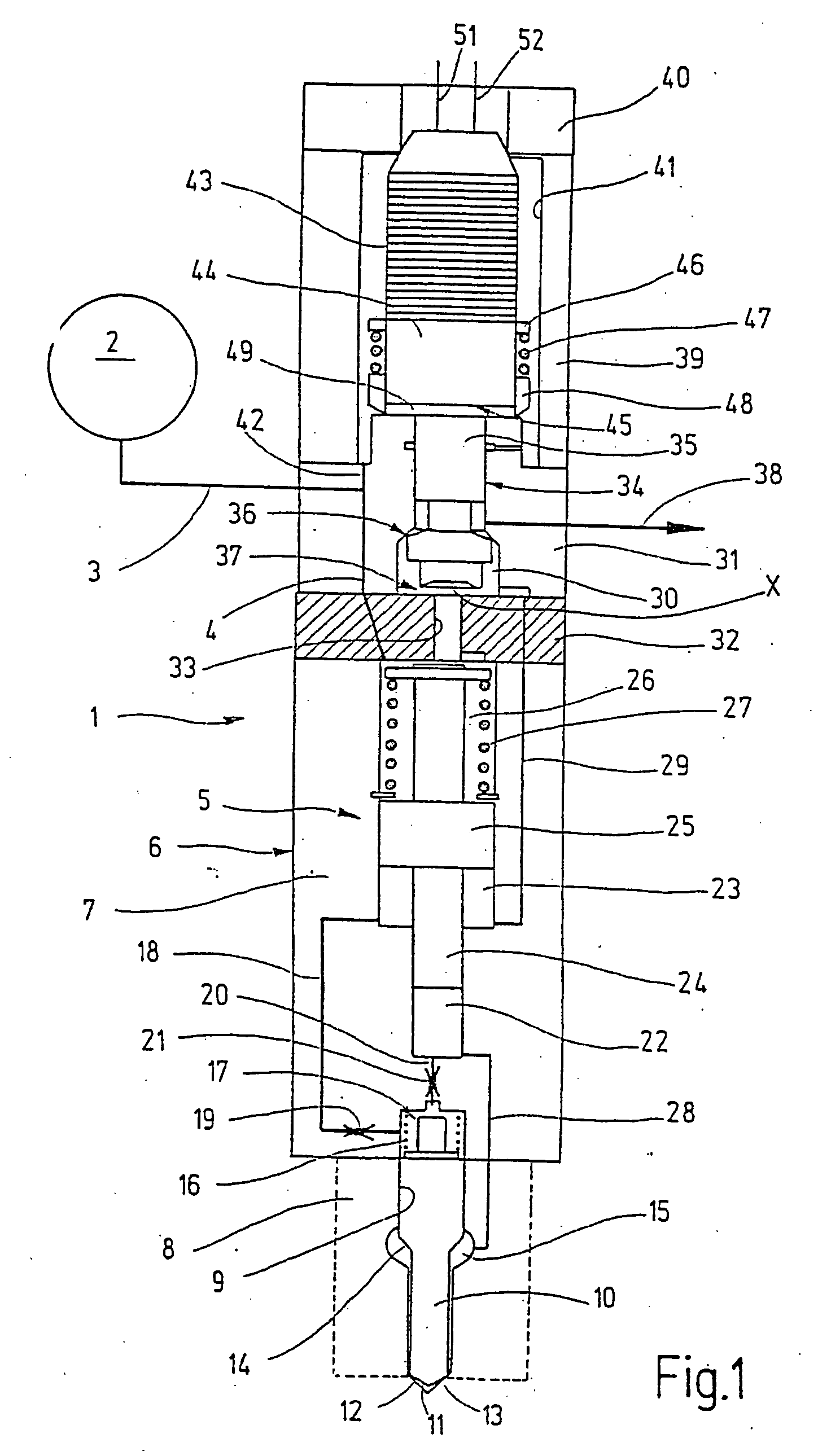
[0018] In FIG. 1, a longitudinal section is shown through a common rail injector 1, which is supplied with fuel that is at high pressure via a high-pressure reservoir 2 (common rail) shown only schematically. From the interior of the high-pressure reservoir 2, a fuel supply line 3, 4 extends to a pressure booster 5, which is integrated into the fuel injector 1. The pressure booster 5 is enclosed by an injector housing 6.

[0019] The injector housing 6 includes an injector body 7 and a nozzle body 8, which has a central guide bore 9. A nozzle needle 10 is guided movably back and forth in the guide bore 9. The nozzle needle 10 has a tip 11, on which a pressure face is embodied that cooperates with a sealing seat that is embodied on the nozzle body 8. When the tip 11 of the nozzle needle 10, with its pressure face, is in contact with the sealing seat, a plurality of injection ports 12, 13 in the nozzle body 8 are closed. When the nozzle needle tip 11 lifts from its seat, fuel subjected ...


PUM


Abstract

A common rail injector having an injector housing having a fuel supply line which communicates with a central high-pressure fuel source outside the injector housing and with a pressure chamber inside the injector housing, from which pressure chamber, as a function of the position of a 3 / 2-way control valve, fuel subjected to high pressure is injected. The 3 / 2 way control valve, includes a valve piston, movable back and forth in the injector housing between a position of repose and an injection position, which piston is coupled hydraulically with a piezoelectric actuator that is subjected to the pressure from the high-pressure fuel source.

Description

[0001] The invention relates to a common rail injector for injecting fuel into a combustion chamber of an internal combustion engine, having an injector housing, which has a fuel supply line which communicates with a central high-pressure fuel source outside the injector housing and with a pressure chamber inside the injector housing, from which pressure chamber, as a function of the position of a control valve, especially a 3 / 2-way valve, fuel subjected to high pressure is injected. PRIOR ART [0002] From German Published Patent Application DE 102 29 415 A1, a pressure-boosted fuel injector is known, which is supplied with fuel at high pressure via a high-pressure reservoir. From the interior of the high-pressure reservoir, a supply line leads to a pressure booster, which is integrated into the fuel injector. The pressure booster is enclosed by an injector body of the fuel injector. The fuel injector further includes a metering valve, which is embodied as a 3 / 2-way valve. The meteri...

Claims


Application Information

Patent Timeline
Patent Type & Authority Applications(United States)
IPC IPC(8): F02M51/00F02M47/00F02M47/02F02M59/46F02M63/00F02M63/02
CPCF02M47/00F02M47/027F02M2547/006F02M63/0026F02M63/0045F02M63/0007
Inventor MAGEL, HANS-CHRISTOPH
Owner ROBERT BOSCH GMBH
Why Eureka
Try Eureka