[0004]It is the task of the invention to simplify the manufacturing of a valve plate according to the
preamble of claim 1. Further, a reciprocating compressor shall be provided, which is simple and cheap in manufacturing.
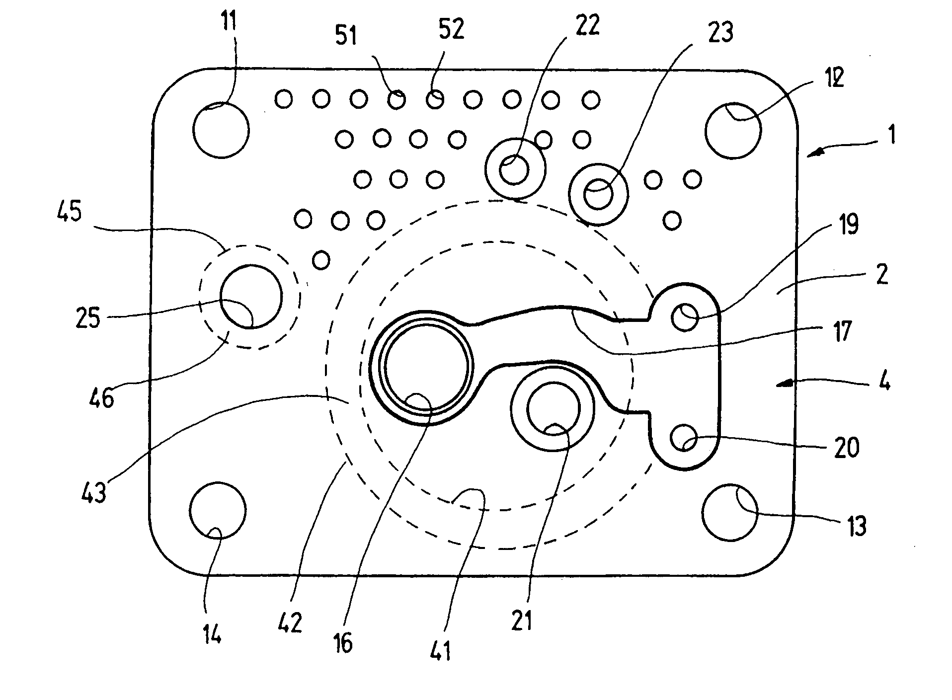
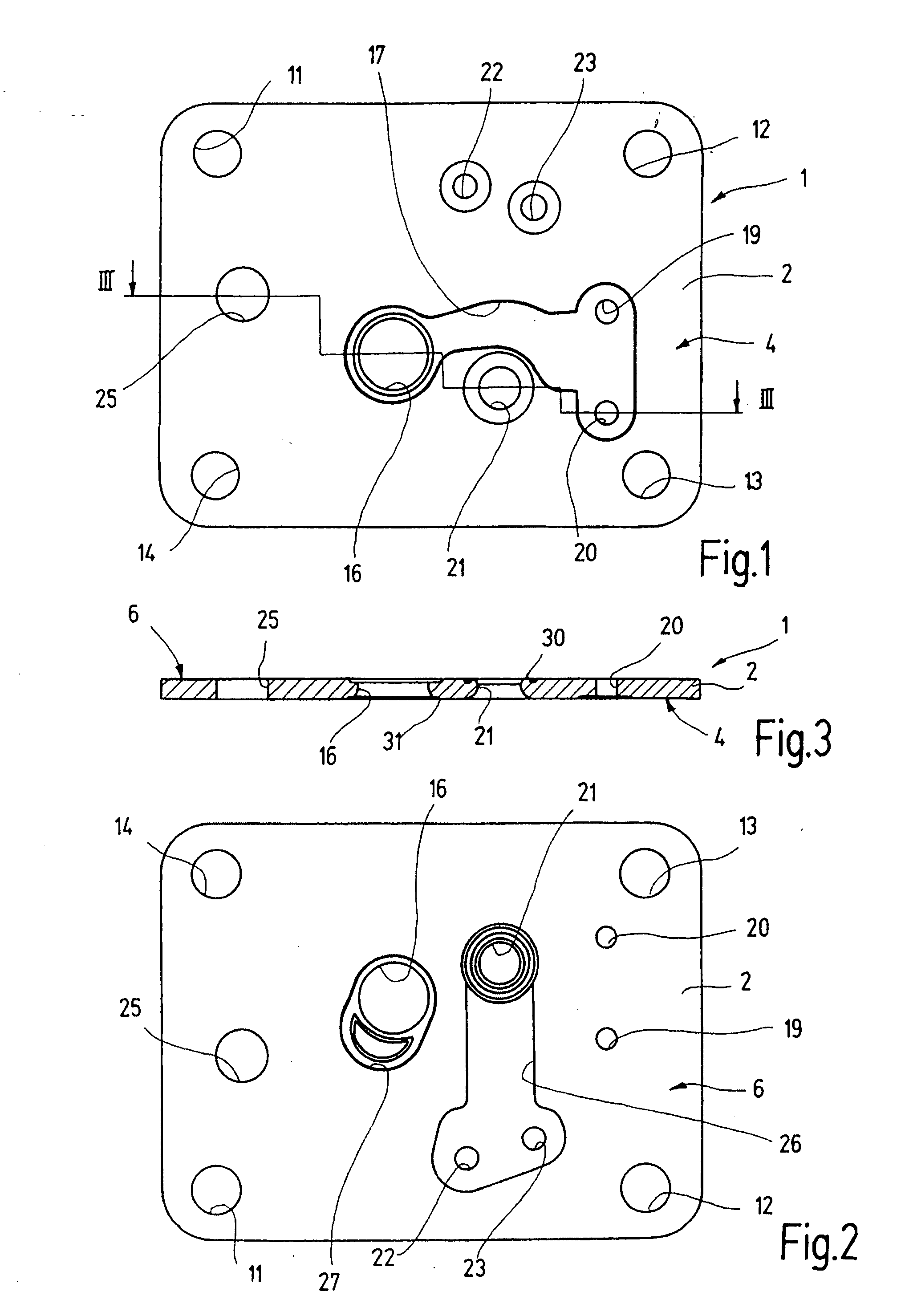
[0005]With a valve plate for a reciprocating compressor, the valve plate being a sintered part having on at least one valve plate surface at least one
valve seat surface worked after
sintering, this task is solved in that the valve plate surface has at least one defined area portion with a relatively uneven surface and at least one defined area portion with a relatively even surface. Making defined area portions with different degrees of evenness, enables optimal
adaptation of the various area portions of the valve plate surface to their individual functions. The relatively even surface has a very narrow tolerance range with evenness tolerances in the μm-range. The relatively uneven surface can have recesses and / or projections in a wide tolerance range with evenness tolerances of several hundredths mm.
[0006]A preferred embodiment of the valve plate is characterised in that compared to the at least one defined area portion with the relatively even surface, the at least one defined area portion with the relatively uneven surface is so large that the valve plate surface concerned can be manufactured in one stamping step. It is difficult or impossible to make the complete valve plate surface with a relatively even surface in one single stamping step. Therefore, valve plates of
sheet steel as known from the international
patent application WO 01 / 63126 A1 are made in subsequent
punching and stamping steps. With sintered valve plates as known from the German publication DE 40 39 786 C2, the valve seats and the recesses for the valves are stamped during a first calibration step after the sintering. Subsequently, the remaining surface of the valve plate is grinded, before the valve seats and the recesses for the valves are redone during a second calibration step. Here, the burrs occurring during
grinding must be removed. The second calibration step can be made by stamping, lapping or rolling. By dividing the valve plate surface into area portions with different degrees of evenness according to the invention, the expensive
machining process can be avoided. This involves the
advantage that, for example, a valve plate surface sealed by means of a steam treatment is not damaged during
machining.
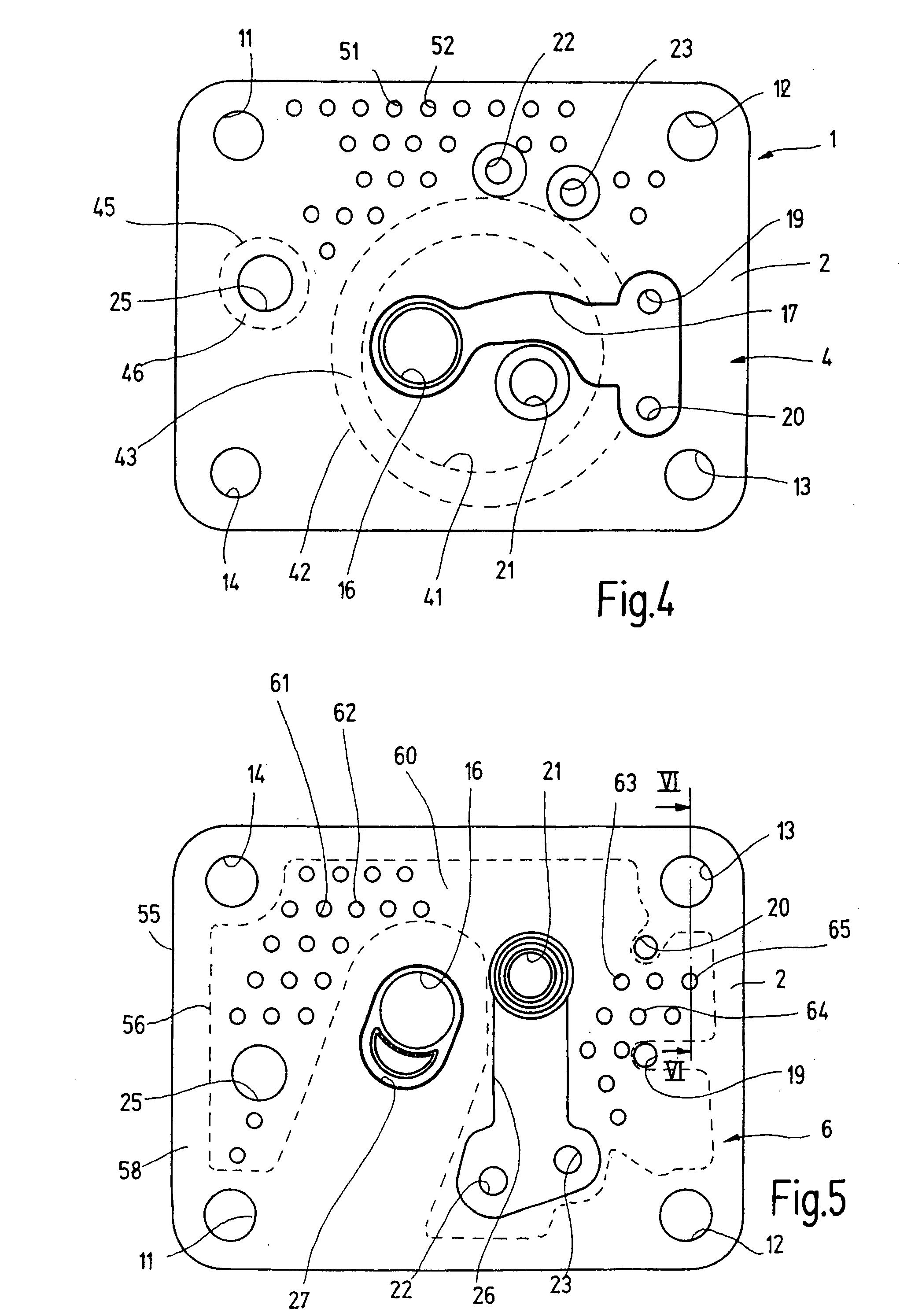
[0007]A further preferred embodiment of the valve plate is characterised in that the at least one defined area portion with the relatively uneven surface is larger than the at least one defined area portion with the relatively even surface. This substantially simplifies the stamping of the valve plate surface. Preferably, the at least one defined area portion with the relatively uneven surface is distinctly larger than the at least one defined area portion with the relatively even surface.
[0015]A method for manufacturing a previously described valve plate involves the following steps: A preferably powdery sintering material is pressed to form a blank; the sintering material can, for example, be an unalloyed sintering iron available as
powder; during the pressing the blank is provided with through-holes and / or recesses. Subsequently, the blank is sintered. According to an essential aspect of the invention, the sintered blank is then stamped during one single method step. As the manufacturing process according to the invention requires no further
grinding, lapping or other
machining processes over the entire surface, annular projections or beads can be made in the sealing surfaces or sealing sections or sealing zones, such projections or beads improving the tightness of a reciprocating compressor provided with such a valve plate.
[0019]With a device for stamping a valve plate surface of a previously described valve plate by a previously described method by means of a stamping tool, the task stated above is solved in that the stamping tool has a plurality of projections, which serve the purpose of providing indentations in the at least one defined area portion with a relatively uneven surface. In the area of the indentations, the usually porous sintering material is locally compressed during stamping. This involves the
advantage that during stamping excess material is adopted in the valve plate itself, or displaced into available unevennesses. In this simple manner, predetermined thickness and / or evenness tolerances can be observed.

