Liquid crystal display apparatus and backlight unit used in liquid crystal display apparatus

a liquid crystal display and backlight technology, applied in the direction of instruments, static indicating devices, etc., can solve the problems of patent document 1 failing to disclose the fixation method of optical sensors, and achieve the effect of reducing the noise level, reducing the variation of detection levels, and reducing the deviation of detection levels

Inactive Publication Date: 2007-09-27
NEC LCD TECH CORP
View PDF8 Cites 13 Cited by
  • Summary
  • Abstract
  • Description
  • Claims
  • Application Information

AI Technical Summary

Benefits of technology

[0022]According to the present invention, an optical sensor is provided in a side surface of a light guide plate so as to directly detect light within the light guide plate. Accordingly, a positional relationship between the light guide plate and the optical sensor is integrally fixed. Specifically, the positional relationship between the light guide plate and the optical sensor is unlikely to be subjected to an external influence. When a supply current to a light source is controlled by a detection level sensed with this configuration, it is possible to reduce a variation of a detection level due to changes of the positional relationship.
[0023]Furthermore, according to an embodiment of the present invention, resin containing a dispersing agent is disposed on a light-receiving portion. Resin for light shield is disposed around the sensor and fixed together with the optical sensor and a color filter. With this configuration, it is possible to prevent light having no directivity and biased light from being introduced into the light-receiving portion of the sensor. Moreover, it is also possible to reduce a detection deviation due to entry of external light from side surfaces of the sensor or the like. Accordingly, a level of noise can be reduced so as to provide a signal level required for detection. As a result, the control of the liquid crystal display apparatus is facilitated.

Problems solved by technology

However, Patent Document 1 fails to disclose how to fix the optical sensor.

Method used


Image

  • Liquid crystal display apparatus and backlight unit used in liquid crystal display apparatus
  • Liquid crystal display apparatus and backlight unit used in liquid crystal display apparatus
  • Liquid crystal display apparatus and backlight unit used in liquid crystal display apparatus

Examples


first embodiment

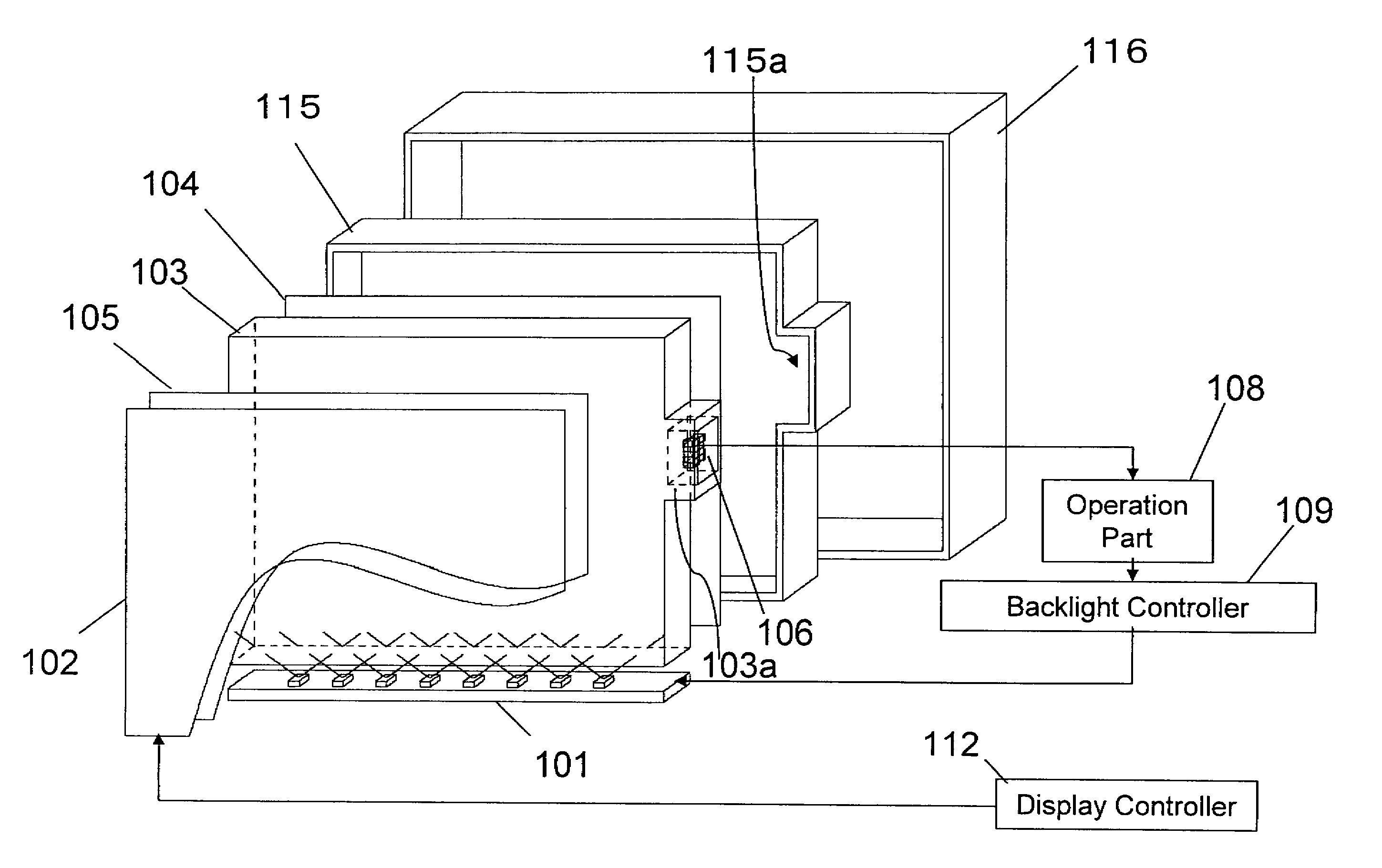
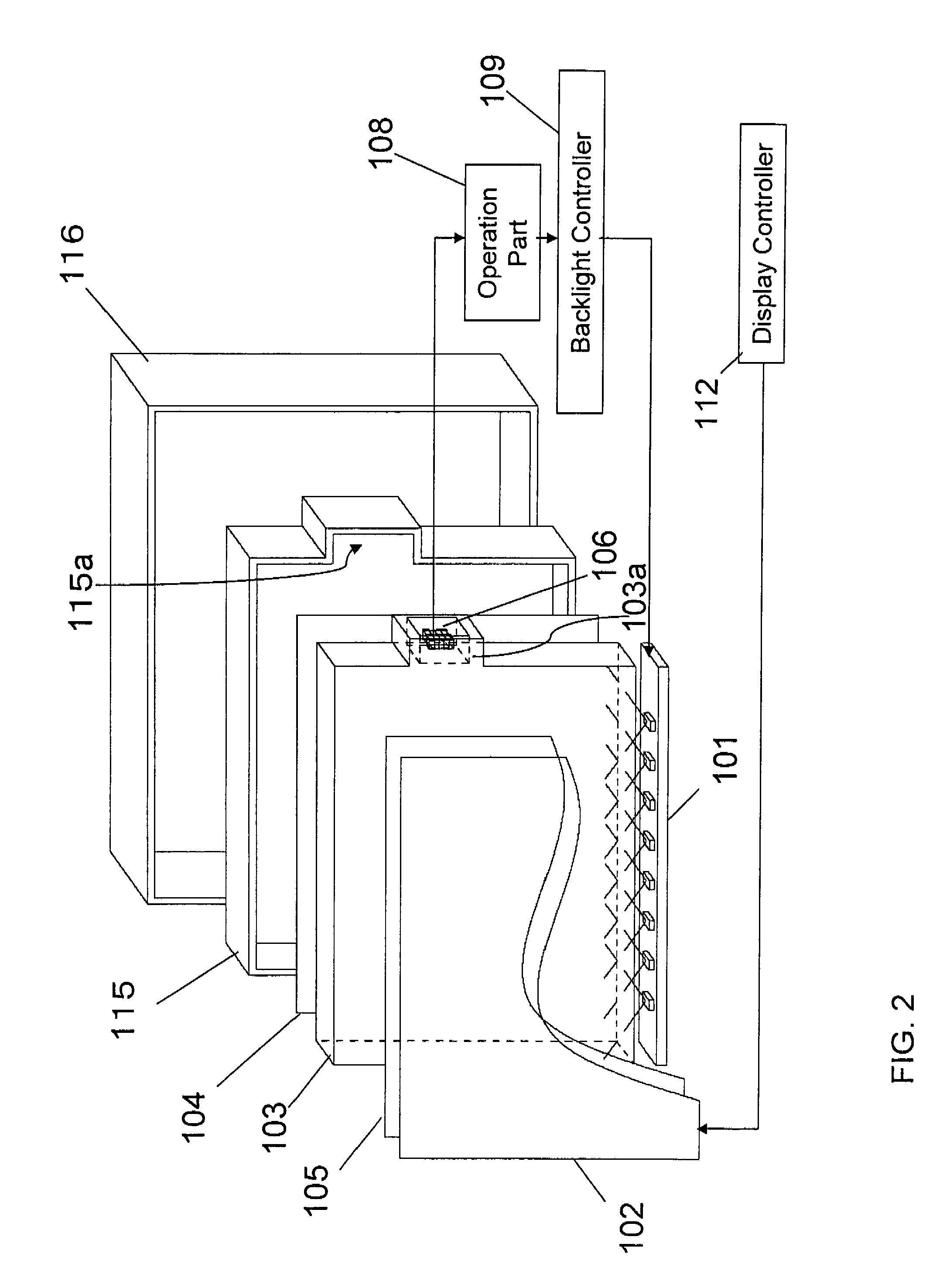
[0029]FIG. 2 is an exploded perspective view schematically showing a liquid crystal display apparatus according to the present invention.

[0030]As shown in FIG. 2, the liquid crystal display apparatus includes a liquid crystal panel 102, a LED light source 101, an optical sheet 105, a light guide plate 103, and a reflector plate 104. The liquid crystal display apparatus also includes an inner case 115, which serves as a case for a backlight unit. The liquid crystal display apparatus includes an outer case 116, which serves as a monitor frame housing the backlight unit and the liquid crystal panel 102. The light guide plate 103 is formed of a transparent material, such as acrylic resin, having substantially a rectangular parallelepiped shape. The LED light source 101 is disposed on a lower surface of the light guide plate 103. Light emitted from the LED light source 101 is introduced into the light guide plate 103 from the lower surface of the light guide plate 103, reflected within t...

second embodiment

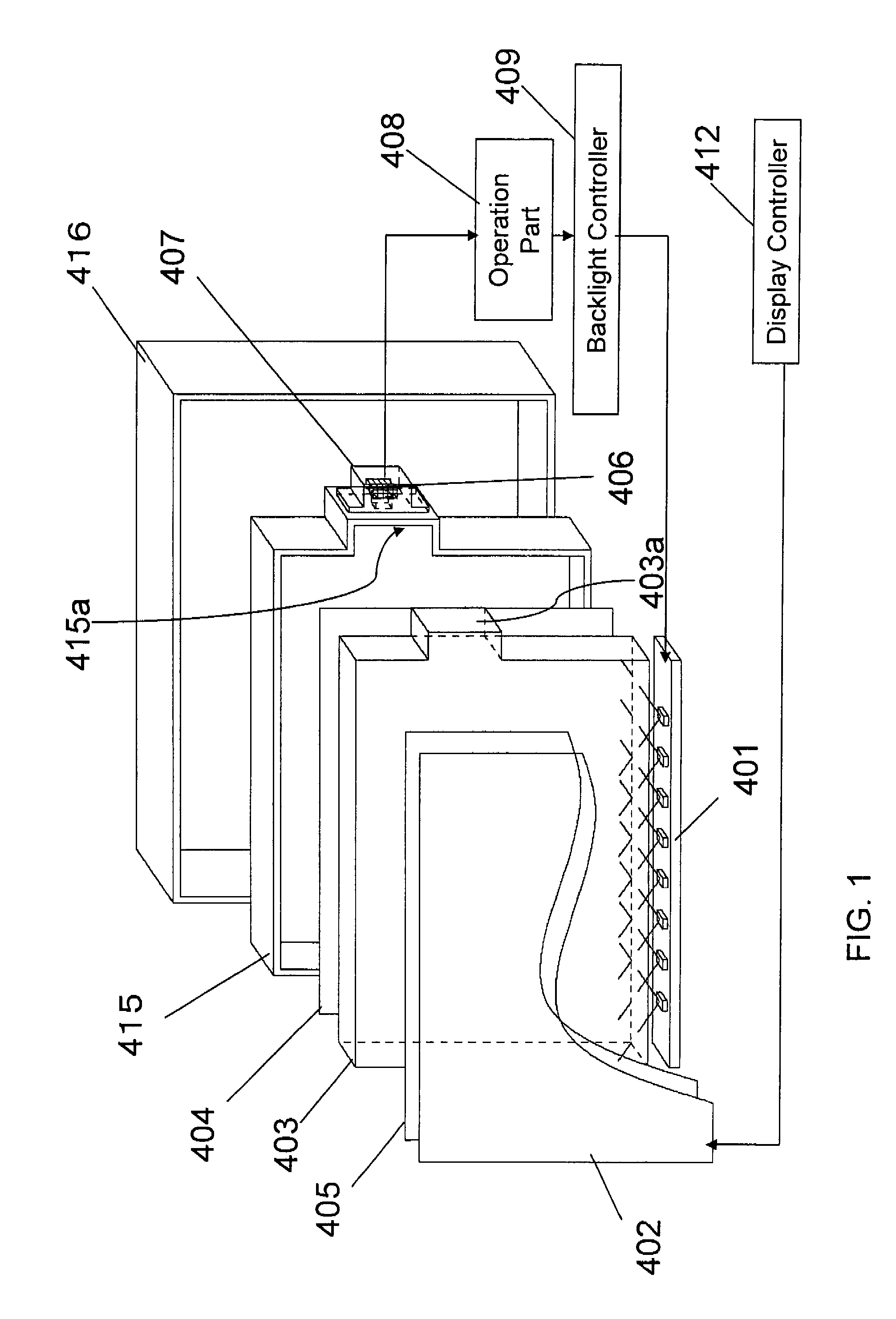
[0042]FIG. 4 is an exploded perspective view schematically showing a liquid crystal display apparatus according to the present invention.

[0043]The second embodiment shown in FIG. 4 differs from the first embodiment shown in FIG. 2 in that a synchronizing signal circuit 130 is provided in the liquid crystal display apparatus. Components including a liquid crystal panel, a light guide plate, an LED light source, an optical sheet, a reflector plate, a light guide plate, and an optical sensor unit provided integrally on the light guide plate are the same as those in the aforementioned first embodiment and are thus omitted from the following description, which is focused on differences from the first embodiment.

[0044]The liquid crystal display apparatus in the present embodiment employs field sequential color (FSC) technique in which each color of red, green and blue displayed on a liquid crystal panel is synchronized with each color of light emission from red, green and blue light sourc...


PUM


Abstract

A display apparatus provides an improved control accuracy of the brightness and the chromaticity. The liquid crystal display apparatus has a liquid crystal panel and a backlight unit for applying diffused light to the liquid crystal panel in a form of a sheet. The backlight unit has a light source, a light guide plate for converting light emitted from the light source into a sheetlike beam of light, an optical sheet for converting light emitted from the light guide plate into condensed light or diffused light, and an optical sensor unit for detecting a portion of light from the light guide plate and converting the detected light into an electric signal. The backlight unit also has a case housing the light source, the light guide plate, the optical sheet, and the optical sensor unit. The optical sensor unit is fixed to an area that is inside of the light guide plate and exerts no influence on display.

Description

[0001]This application claims priority to prior Japanese patent application JP2006-078018, the disclosure of which is incorporated herein by reference.BACKGROUND OF THE INVENTION[0002]1. Field of the Invention[0003]The present invention relates to a liquid crystal display apparatus, and more particularly to a liquid crystal display apparatus having a function of controlling a brightness or a chromaticity with an optical sensor and a backlight unit used in such a liquid crystal display apparatus.[0004]2. Description of the Related Art[0005]A liquid crystal display apparatus employs technology of controlling a light source for adjusting a brightness or a chromaticity of light applied to a liquid crystal panel to a desired level. For example, Japanese laid-open patent publication No. 2004-199968 (Patent Document 1) discloses such a liquid crystal display apparatus.[0006]According to Patent Document 1, light is applied from a sheetlike light source device to an entire surface of a liqui...

Claims


Application Information

Patent Timeline
Patent Type & Authority Applications(United States)
IPC IPC(8): G09G3/36
CPCG09G3/3406G09G2320/0626G09G2320/0666G09G2360/145
Inventor ITAYA, HIDEKI
Owner NEC LCD TECH CORP
Why Eureka
Try Eureka