Light redirecting film

a technology of redirecting film and light, applied in the field of optical films, can solve the problems of insatiable lcds, inoptimum light, waste of materials, etc., and achieve the effects of maximizing optical efficiency, low cost, and easy manufacturing

Inactive Publication Date: 2007-09-27
ROHM & HAAS DENMARK FINANCE
View PDF5 Cites 18 Cited by
  • Summary
  • Abstract
  • Description
  • Claims
  • Application Information

AI Technical Summary

Benefits of technology

[0045] This invention provides a simplified and integrated light redirecting film that leads to easy manufacturing and low cost. This invention also maximizes optical efficiency so as to enhance brightness as well as viewing angle. ...

Problems solved by technology

While liquid crystal displays (LCDs) offer a compact, lightweight alternative to cathode ray tube (CRT) monitors, there are many applications for which LCDs are not satisfactory due to a low level of brightness, or more properly, luminance.
Necessarily, this type of approach is somewhat of a compromise; such an approach is not optimal for light in directions diagonal to the two orthogonal axes.
However, some of the reflected light is absorbed by materials and lost in reflection during recycling.
For the most part, these films exhibit directional bias, with some of the light poorly directed.
Existing light redirecting layers, in an effort to achieve higher on-axis brightness, often compromise display uniformity so that, for example, an LC display appears very bright when viewed from a normal direction but is dim when viewed from off-normal angles.
This can res...

Method used


Image

  • Light redirecting film
  • Light redirecting film
  • Light redirecting film

Examples


Embodiment Construction

[0076] In the following detailed description, for purposes of explanation and not limitation, example embodiments disclosing specific details are set forth, in order to provide a thorough understanding of the present teachings. However, it will be apparent to one having ordinary skill in the art that other embodiments that depart from the specific details disclosed herein are possible. Moreover, descriptions of well-known devices, methods, and materials may be omitted so as to not obscure the description of the example embodiments. Nonetheless, such devices, methods, and materials that are within the purview of one of ordinary skill in the art may be used in accordance with the example embodiments.

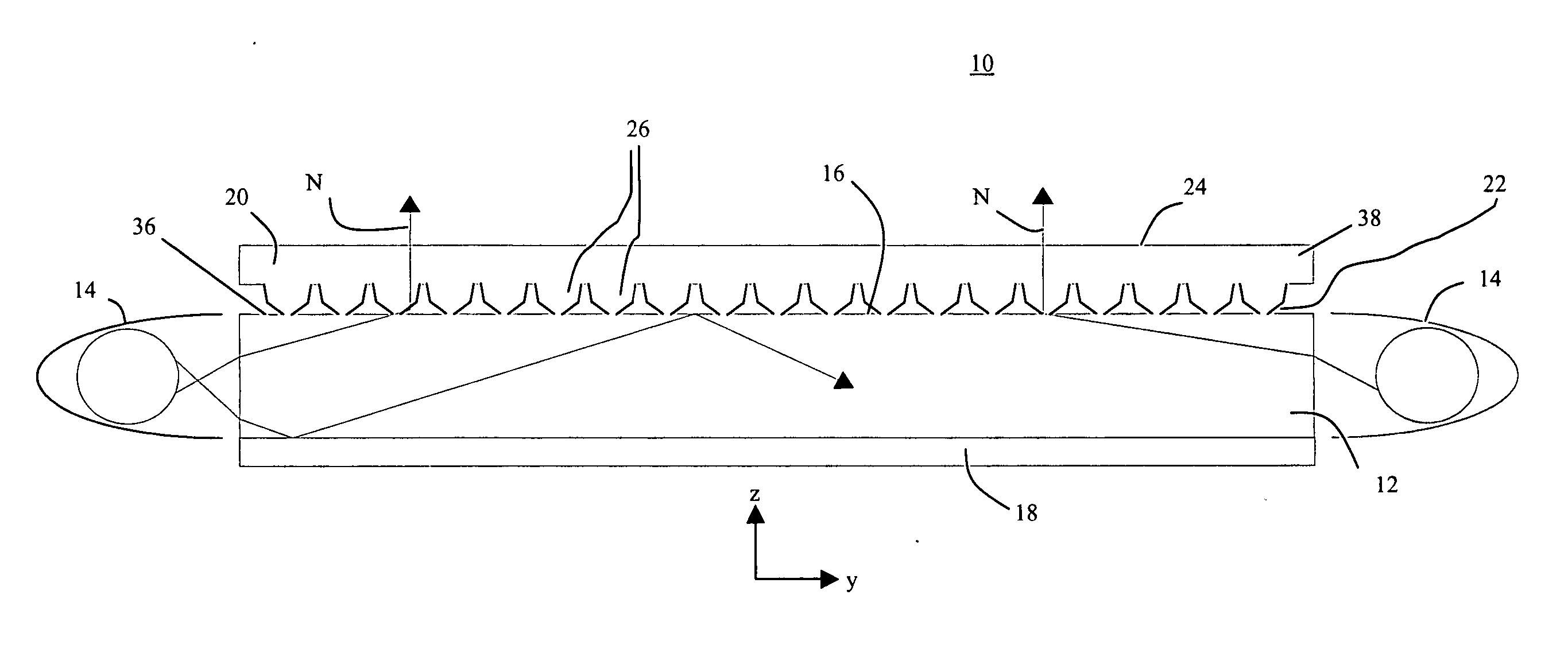
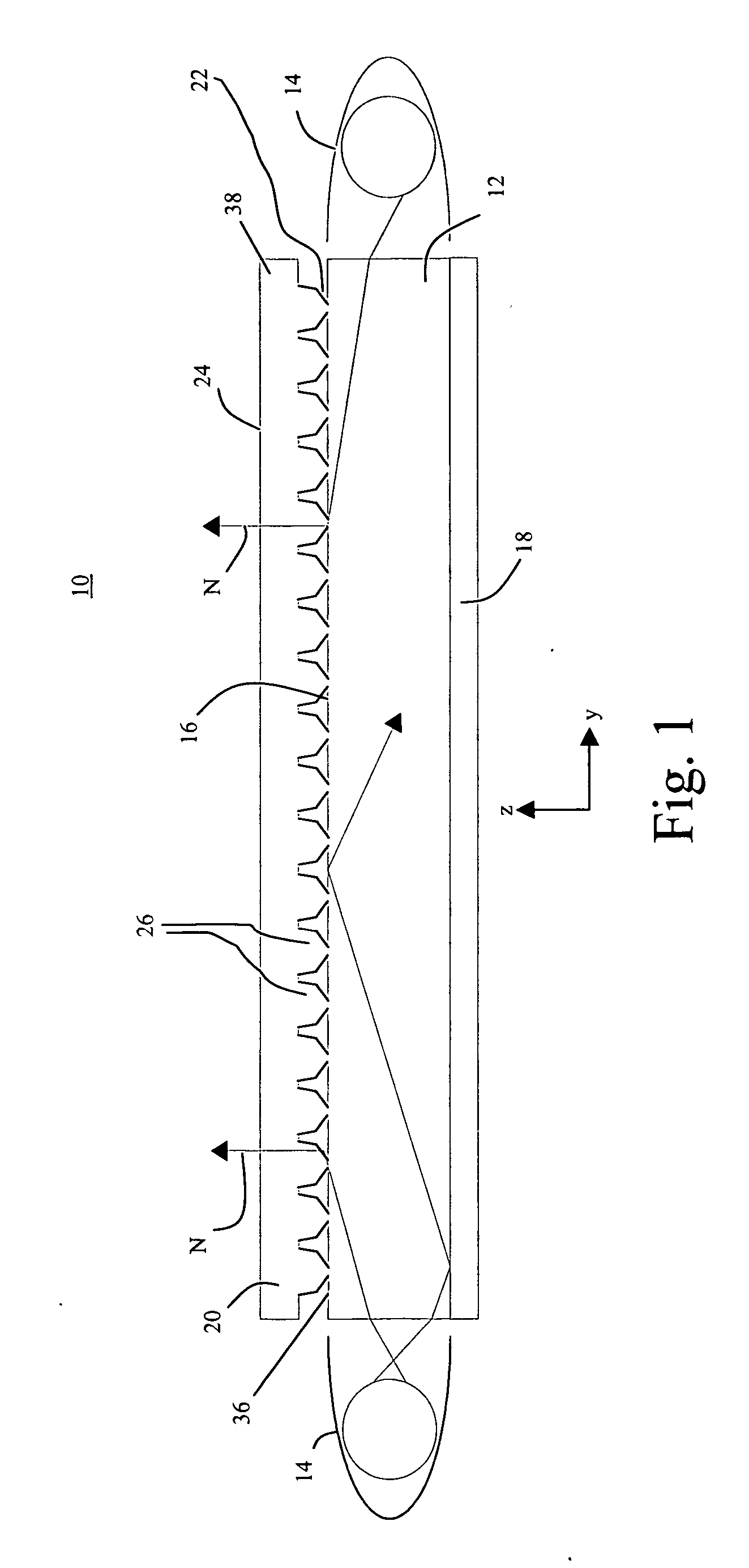
[0077]FIG. 1 is a cross-sectional view of an illumination apparatus 10 having a light redirecting film 20 optically coupled to the top surface 16 of a light guide 12 in one embodiment, typically coupled using a layer of optical adhesive 36. Light sources 14, typically cold-cathode fluores...


PUM


Abstract

This invention relates to an illumination apparatus comprising: (a) at least one light source; (b) a light guide for accepting light from the at least one light source and for guiding the light using total internal reflection, the light guide having a top surface; (c) a light redirecting film having an input surface optically coupled with the top surface and an output surface for providing redirected light, wherein the input surface comprises a plurality of light redirecting features which are optically coupled to the top surface, each light redirecting feature having: (i) a first side comprising two or more planar segments; and (ii) a second side comprising two or more planar segments, wherein the first and second sides intersect at an apex.

Description

FIELD OF THE INVENTION [0001] The present invention generally relates to optical films, and more particularly relates to a light redirecting film using an arrangement of light redirecting structures for conditioning illumination for use in display and lighting applications. BACKGROUND OF THE INVENTION [0002] While liquid crystal displays (LCDs) offer a compact, lightweight alternative to cathode ray tube (CRT) monitors, there are many applications for which LCDs are not satisfactory due to a low level of brightness, or more properly, luminance. The transmissive LCD that is used in known laptop computer displays is a type of backlit display, having a light-providing surface positioned behind the liquid crystal (LC) array for directing light outwards, towards the LCD. The light-providing surface itself provides illumination that is essentially Lambertian, having an essentially constant luminance over a broad range of angles. [0003] With the goal of increasing on-axis and near-axis lum...

Claims


Application Information

Patent Timeline
IPC IPC(8): F21V7/04
CPCG02B6/0061G02B6/0053
Inventor LEE, JUNWONWILSON, RANDALL H.MEISSNER, STEPHEN C.
Owner ROHM & HAAS DENMARK FINANCE
Why Eureka
Try Eureka