Oscillating grinding machine

a technology of oscillating grinding machine and grinding machine, which is applied in the direction of grinding machine components, grinding machine abrading process, grinding machine parts, etc., can solve the problems of increasing the difficulty of repairing surface defects, increasing the difficulty of grinding product outer edge grinding significantly more efficiently than the middle area of grinding product, and affecting the quality of grinding produ

Active Publication Date: 2007-09-27
KWH MIRKA
View PDF18 Cites 11 Cited by
  • Summary
  • Abstract
  • Description
  • Claims
  • Application Information

AI Technical Summary

Problems solved by technology

The problem in known grinding machines that comprise the above-described two-dimensional and plane oscillation movement is that the outer edge of the grinding product is grinding significantly more efficiently than the middle area of the grinding product.
This further increases the difficulty of repairing said surface defects.
A grinding machine of the above type also often tends to be unsteady or sway.
The insufficient prevention causes the grinding machine to sway, which, in turn, leads to a situation wherein the fastening plate and the grinding product fastened thereto cannot at all times bear completely straight against the surface to be ground.
The problems of these uneven grinding results are further accentuated by the difficulty at the start of the grinding work to dispose the fastening plane of the grinding machine with the grinding product completely straight against the surface to be ground.
The result of all these above problems and shortcomings is that new surface defects in the form of finishing defects are often created during a grinding work with known oscillating tools.
These finishing defects comprise crater-like recesses at the outer edge of the grinding area.
These finishing defects are particularly troublesome when an attempt is made to remove a small defect in the surface lacquering of a car, for example.
The patent discloses a detailed construction with an adjustable drive shaft, which renders the machine both difficult to balance and difficult to implement.
The contemplated area of use of the machine results in a construction that renders it impossible to utilize the grinding machine in grinding at very high speeds of rotation.

Method used


Image

  • Oscillating grinding machine
  • Oscillating grinding machine

Examples


Embodiment Construction

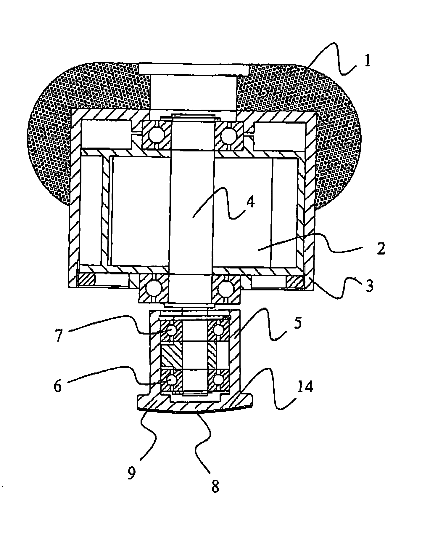
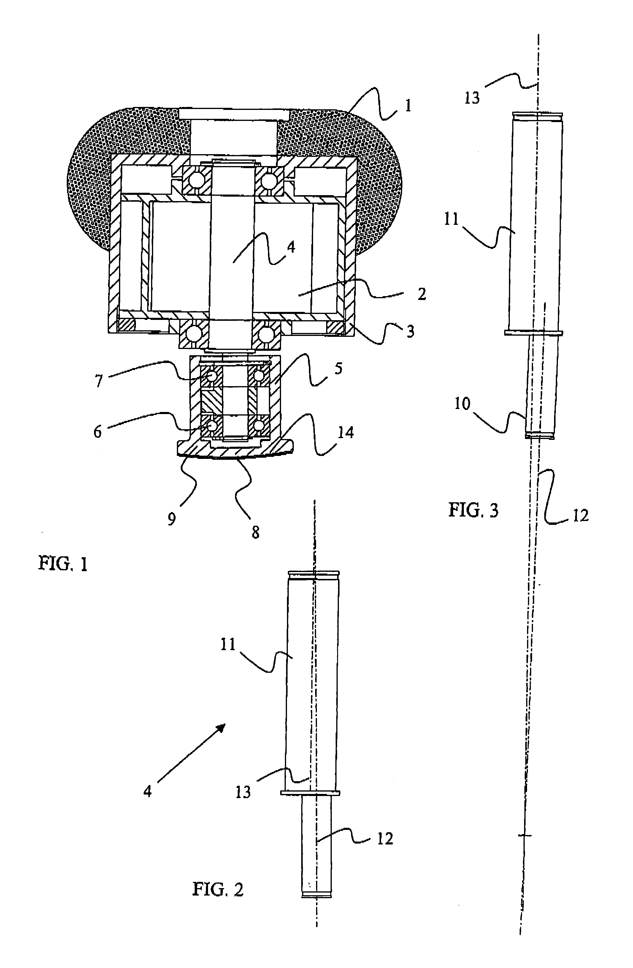
[0024] Preferred embodiments of the present oscillating grinding machine are described below with reference to the above-mentioned figures. Herein, the solutions comprise the constructional parts shown in the figures, each of which are denoted with a respective reference numeral. These reference numerals correspond to the reference numerals given in the following description.

[0025] According to FIG. 1, an oscillating grinding machine comprises a stem 1 surrounding a driving motor 2 together with a body 3. The driving motor controls a drive shaft 4 that cooperates with a grinding head 5. The grinding machine may be provided with either an electric or a pneumatic driving motor, which controls the drive shaft at a suitable speed. The drive shaft rotates usually at a rotation speed of 1,000 to 12,000 rpm. The drive shaft is preferably arranged to be directly driven by the driving motor. An alternative implementation of an oscillating grinding machine for very small tasks is designed as...


PUM

PropertyMeasurementUnit
distanceaaaaaaaaaa
distanceaaaaaaaaaa
radiusaaaaaaaaaa

Abstract

The present invention relates particularly to an oscillating grinding machine. The grinding machine comprises a driving motor (3) surrounded by a body (3), and a drive shaft (4) cooperating with the driving motor. The drive shaft comprises a grinding head (5) that constitutes a support for a grinding product (8). The drive shaft (4) is arranged in two pieces and comprises a main shaft (11) and an eccentric shaft (10) arranged rigidly thereto. The eccentric shaft comprises a centre line (12) that assumes an angle (α) against a corresponding centre line (13) of the main shaft, and thus the grinding head (5) will assume an eccentric placement in relation to the main shaft (11). Thus, the grinding head is arranged to oscillate in a substantially spherical plane provided by the rotation of the main shaft and the eccentricity and inclination of the eccentric shaft in relation to the main shaft.

Description

TECHNICAL FIELD [0001] The present invention relates to an oscillating grinding machine according to the preamble of claim 1 that generates a spherical oscillation. The machine is primarily intended for grinding small defects in colour and lacquer with abrasive discs or the like grinding products that have a small dimension, but the invention can also be utilized for grinding products having surfaces with a concave or convex cap form. PRIOR ART [0002] It is generally known to perform grinding with different types of oscillating tools in repairing work involving colour or lacquer damage. Because such repairing work often relates to the machining of surfaces having small areas, the work is preferably performed with easily handled manually operated grinding machines. For the execution of the work, a grinding product, for example an abrasive disc, is fastened to the upper surface of a fastening plate that is comprised by the tool and caused to oscillate through an eccentric operating in...

Claims


Application Information

Patent Timeline
Patent Type & Authority Applications(United States)
IPC IPC(8): B24B23/00
CPCB24B11/00Y10S451/921B24B41/04B24B23/03B24B23/04B24B35/00B24B1/00B24B1/04
Inventor HOGLUND, GORAN
Owner KWH MIRKA
Why Eureka
Try Eureka