Automatic tool changing method and device for machine tool controlled by numerical controller

a numerical controller and tool changer technology, applied in the direction of manufacturing tools, metal-working machine components, transportation and packaging, etc., can solve the problems of increasing parts as well as assembly costs, affecting the durability of constituent parts, and generating dust in the machining of machine tools, so as to eliminate the problems of the durability of the constituent parts and facilitate the exchange of tools. , the effect of simple construction

Active Publication Date: 2007-09-27
FANUC LTD
View PDF13 Cites 26 Cited by
  • Summary
  • Abstract
  • Description
  • Claims
  • Application Information

AI Technical Summary

Benefits of technology

[0032]The velocity of the spindle head is controlled so as to perfect the swing of the turret, and therefore nimble and fast tool exchange is achieved. At the same time, the lift mechanism that is required conventionally becomes unnecessary, eliminating problems relating to the durability of the constituent pa...

Problems solved by technology

However, machine tools generate dust when machining, and since this dust adheres to the cam groove (CL) the cam groove (CL) head must be cleaned.
Further, the cam mechanism (the lift lever 8, the lift link 14, the lift slider 16, the l...

Method used


Image

  • Automatic tool changing method and device for machine tool controlled by numerical controller
  • Automatic tool changing method and device for machine tool controlled by numerical controller
  • Automatic tool changing method and device for machine tool controlled by numerical controller

Examples


Embodiment Construction

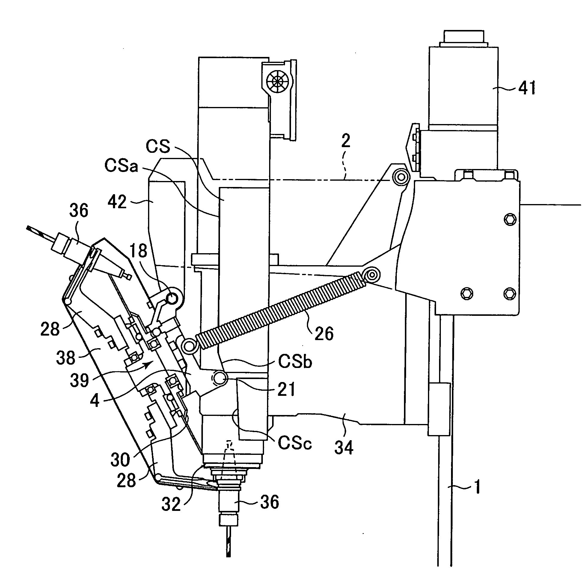
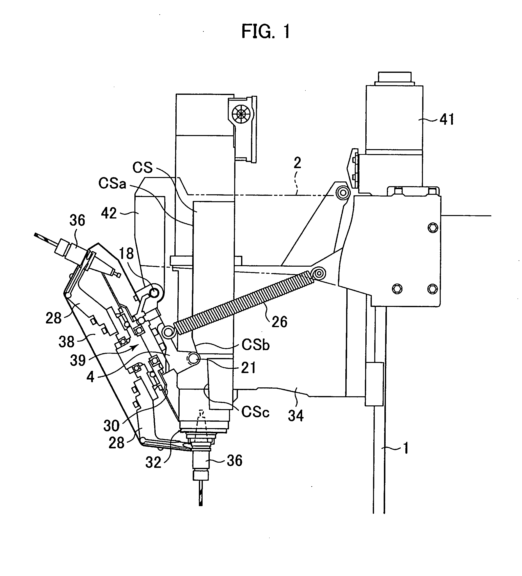
[0045]FIG. 1 is a schematic diagram of an automatic tool changing device of an embodiment of the present invention. Elements identical to those of the conventional automatic tool changer shown in FIG. 11 are given the same reference numerals. The difference between the automatic tool changing device of the present embodiment of the present invention and the conventional automatic tool changer shown in FIG. 11 is that the lift mechanism of the latter, which moves the turret 38 up and down during tool exchange, is not provided in the former. Specifically, the lift lever 8, the lift link 14, the lift slider 16, the lift roller 22, the linear guide 40 and the lift cam CL shown in FIG. 11 are not provided, and moreover, the pivot shaft 18 that pivotally supports the crank 4 so that the latter rotates is mounted on a bracket that is fixedly mounted on the arm member 2. The remainder of the structure is the same as that shown in the conventional automatic tool changer shown in FIG. 11.

[004...


PUM


Abstract

An automatic tool changing method and an automatic tool changing device for a machine tool with a numerical controller capable of reducing the occurrence of impact due to tool exchange with a simple structure. A turret that rotates about a pivot shaft is provided on an arm and holds multiple tools. A swing cam CS that cooperates with a swing roller provided on the turret is provided on a spindle head. As the spindle head descends the turret rotates due to the action of the swing roller and the cam CS and exchanges tools. In order to lessen the impact that occurs at this time, the velocity of the spindle head is controlled. The ideal swing velocity pattern for the turret is obtained, and from this swing velocity pattern the swing position of the turret at each moment is obtained. From the swing roller and cam CS positions at this position the position of the spindle head 34 is obtained. From the acquired spindle head position the spindle head velocity pattern is obtained, and the spindle head is controlled using this velocity pattern. As a result, an ideal swing pattern can be achieved, and therefore no impact arises.

Description

BACKGROUND OF THE INVENTION[0001]1. Field of the Invention[0002]The present invention relates to automatic tool changing method and device for automatically changing tools to be used in a machine tool, and in particular to automatic tool changing method and device for a machine tool controlled by a numerical controller.[0003]2. Description of Related Art[0004]An automatic tool changer for use in a CNC drill of a machine tool controlled by a numerical controller is designed to use the reciprocal vertical motion of a spindle on which the drill is mounted to replace a tool mounted on the spindle with a tool held in a turret. In order to shorten the time required for tool exchange as well as to lessen the impact that occurs during tool exchange, moving the turret in the same direction as the direction in which the spindle head moves when the turret swings to move toward and retreat from the spindle during tool exchange so as to reduce the difference in the relative velocities of the tur...

Claims


Application Information

Patent Timeline
IPC IPC(8): B23Q3/157
CPCB23Q3/15706Y10T483/10Y10T483/1795Y10T483/1755Y10T483/1873B23Q3/15534B23B29/32B23Q1/70B23Q16/022B23Q2220/002
Inventor KOJIMA, KUNIOFUJIMOTO, AKIHIKOKOMIYA, TAKERU
Owner FANUC LTD
Why Eureka
Try Eureka