Exhaust purification with on-board ammonia production

a technology of ammonia production and exhaust gas, which is applied in the direction of mechanical equipment, machines/engines, electric control, etc., can solve the problems of high cost of ammonia on-board production, hazardous storage of ammonia, and specialized equipmen

Inactive Publication Date: 2007-10-04
CATERPILLAR INC
View PDF37 Cites 17 Cited by
  • Summary
  • Abstract
  • Description
  • Claims
  • Application Information

AI Technical Summary

Problems solved by technology

Because of the high reactivity of ammonia, storage of ammonia can be hazardous.
Further, on-board production of ammonia can be costly and may require specialized equipment.
For example, an engine may function less efficiently and with lower power output when rich combustion occurs in one cylinder group.
Furthermore, using the method of the '542 patent, it may be more difficult to provide adequate and controlled air intake to both cylinder groups, and the two cylinder groups, operating as described in the '542 patent, may cause significant engine vibration.

Method used


Image

  • Exhaust purification with on-board ammonia production
  • Exhaust purification with on-board ammonia production
  • Exhaust purification with on-board ammonia production

Examples


Embodiment Construction

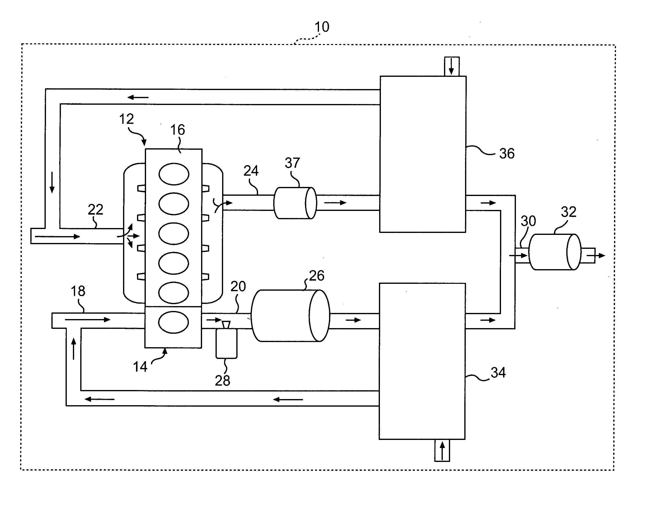
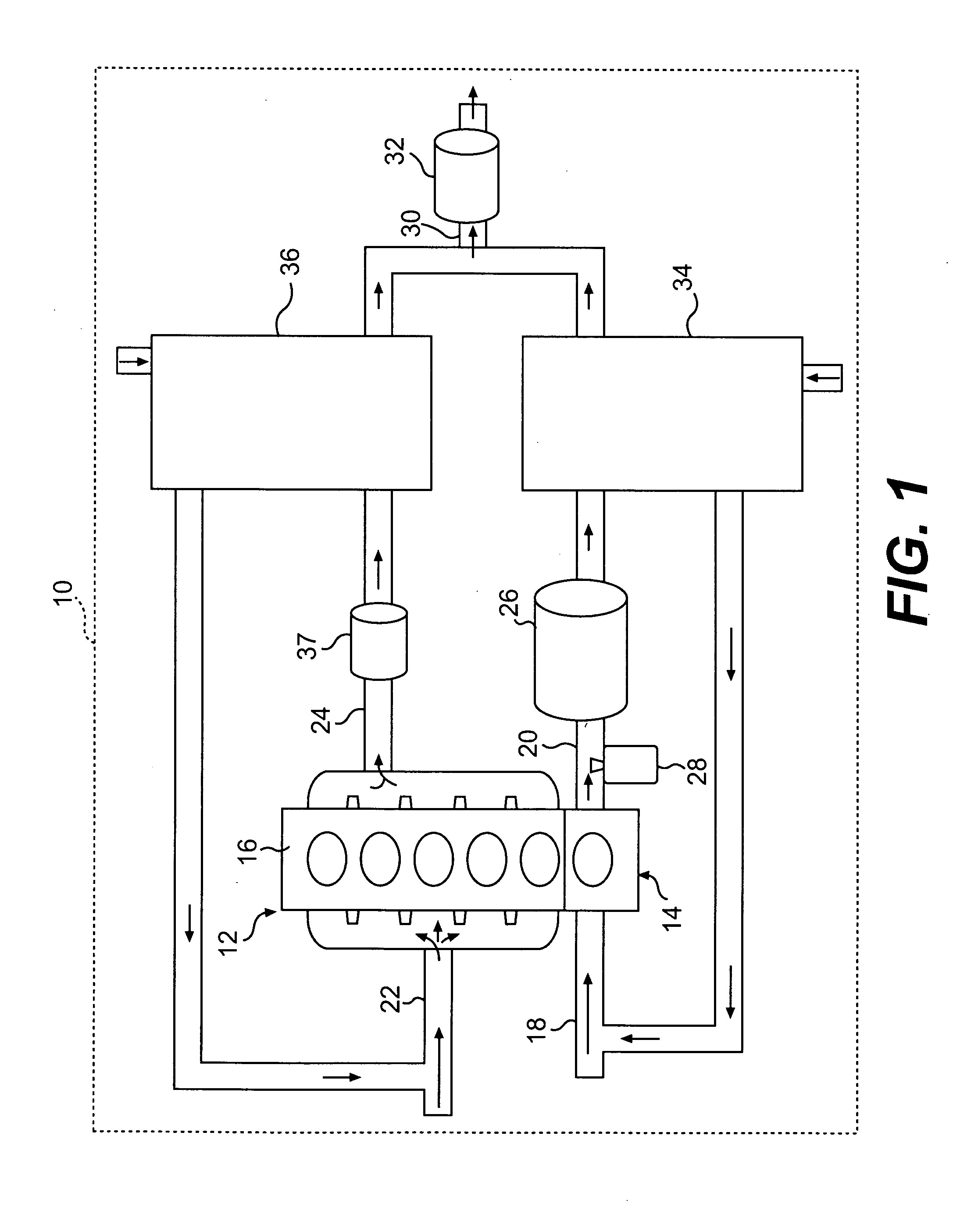
[0024]FIG. 1 provides a schematic representation of a machine 10 of the present disclosure including a power source 12. Power source 12 may include a first cylinder group 14 and a second cylinder group 16. First cylinder group 14 may be fluidly connected to a first air-intake passage 18 and a first exhaust passage 20. Second cylinder group 16 may be fluidly connected to a second air-intake passage 22 and a second exhaust passage 24. In one embodiment, first air-intake passage 18 is fluidly isolated from second air-intake passage 22.

[0025] The operation of engine cylinders may be dependant on the ratio of air to fuel-vapor that is injected into the cylinders during operation. The air to fuel-vapor ratio is often expressed as a lambda value, which is derived from the stoichiometric air to fuel-vapor ratio. The stoichiometric air to fuel-vapor ratio is the chemically correct ratio for combustion to take place. A stoichiometric air to fuel-vapor ratio may be considered to be equivalent...


PUM


Abstract

A first aspect of the present disclosure includes a power source for use with selective catalytic reduction systems for exhaust-gas purification. The power source may comprise a first cylinder group with a first air-intake passage and a first exhaust passage, and a second cylinder group with a second air-intake passage and a second exhaust passage. The power source may further include a first forced-induction system in fluid communication with the first air-intake passage, and a second forced-induction system in fluid communication with the second air-intake passage. A catalyst may be disposed downstream of the fuel-supply device to convert at least a portion of the exhaust stream in the first exhaust passage into ammonia.

Description

[0001] This application is a continuation-in-part of U.S. patent application Ser. No. 11 / 412,834, filed Apr. 28, 2006, which is a continuation-in-part of U.S. patent application Ser. No. 10 / 982,921, filed Nov. 8, 2004, both of which are hereby incorporated by reference.U.S. GOVERNMENT RIGHTS [0002] This invention was made with government support under the terms of Contract No. DE-FC05-00OR22806 awarded by the Department of Energy. The government may have certain rights in this invention.TECHNICAL FIELD [0003] This disclosure pertains generally to exhaust-gas purification systems for engines, and more particularly, to selective catalytic reduction systems with on-board ammonia production. BACKGROUND [0004] Selective catalytic reduction (SCR) provides a method for removing nitrogen oxides (NOx) emissions from fossil fuel powered systems for engines, factories, and power plants. During SCR, a catalyst facilitates a reaction between exhaust-gas ammonia and NOx to produce water and nitro...

Claims


Application Information

Patent Timeline
Patent Type & Authority Applications(United States)
IPC IPC(8): F01N3/10
CPCF01N3/2073F01N2240/25F01N2610/02F01N13/011F02D41/1443Y02T10/144F02B37/007Y02T10/12
Inventor ROBEL, WADE J.DRISCOLL, JAMES JOSHUAEASLEY, WILLIAM L. JR.ROOZENBOOM, STEPHAN D.
Owner CATERPILLAR INC
Why Eureka
Try Eureka