

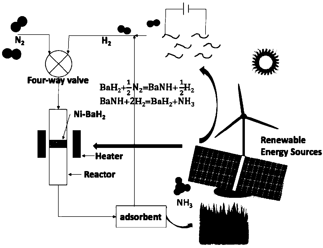
Method for synthesizing ammonia
A technology for synthesizing ammonia and complexes, which is applied in the preparation/separation of ammonia, energy input, etc., and can solve problems such as low efficiency, hydrogen evolution, and difficulty in large-scale application.
- Summary
- Abstract
- Description
- Claims
- Application Information
AI Technical Summary
Problems solved by technology
Method used
Image

Examples
Embodiment 1
[0018] 1) First prepare the materials required for chemical looping. Firstly, the transition metal is supported on Co onto the carrier SiO 2 On, get Co / SiO2;
[0019] Co / SiO 2 The preparation process is: 246.7mg Co(NO 3 ) 2 ·6H 2 O was dissolved in 5 ml of deionized water and then added to 450 mg of SiO 2 Then soak it until all the water volatilizes completely, put it in an oven to dry at 80°C for 10h, and then reduce the obtained sample at 400°C for 5h under a hydrogen atmosphere to obtain a Co / SiO2 sample.
[0020] Then the hydride BaH 2 loaded onto the above material to obtain SiO 2 Loaded Co-BaH 2 Composite materials, Co, BaH 2 , SiO 2 The mass ratio is 1:10:9. H 2 The process of loading onto the above material is: take 49.3mg metal Ba and 50mg reduced Co / SiO 2 The sample is placed in the reactor, and then poured into the reactor with liquid ammonia, soaked for 2 hours, and the liquid ammonia in the reactor is pumped out to obtain Co / SiO 2 -Ba(NH 2 ) 2 samp...
Embodiment 2
[0023] 1) operation process is with embodiment 1 step 1), and embodiment 1 step 1) difference is that metal Ba is changed into Ca; Prepare SiO by above steps 2 Loaded Co-CaH 2 composite material.
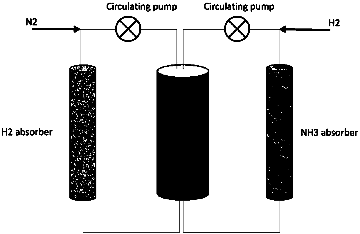
[0024] 2) Take 30 mg of the above-prepared material and put it into a chemical looping reactor, pass high-purity nitrogen into the reactor, control the gas flow rate at 30ml / min, heat the temperature to 250 degrees Celsius, and switch to hydrogen after staying for 1 hour. The hydrogen flow rate is 30ml / min, first pass the tail gas to the conductivity meter to judge how much time is needed for hydrogenation, this material needs to be hydrogenated for 30min. In the latter process, the tail gas after hydrogenation is directly passed to the container containing MgI2, and passes through the MgI2 2 The gas is passed into the conductivity meter. If the conductivity does not change, it means that all the ammonia has been absorbed. Nitrogen feeding for 1 h and hydrogen gas feeding for 30 ...
Embodiment 3
[0026] 1) The operation process is the same as in Example 1 step 1), and the difference from Example 1 step 1) is that metal Ba is replaced by Li;
[0027] 2) Prepare SiO according to the above steps 2 Supported Co-LiH composites. Take 30 mg of the above-prepared material and put it into a chemical looping reactor, pass high-purity nitrogen into the reactor, control the gas flow rate at 30ml / min, heat the temperature to 250 degrees, switch to hydrogen after staying for 1h, and the hydrogen flow rate is 30ml / min min, first pass the exhaust gas to the conductivity meter to judge how long it takes for hydrogenation, this material takes 60 minutes. In the latter process, the tail gas after hydrogenation is directly passed to the 2 container, after MgI 2 The gas is passed into the conductivity meter. If the conductivity does not change, it means that all the ammonia has been absorbed. Repeat 1 h of nitrogen feed and 1 h of hydrogen feed at the above time. After 10 cycles, by w...
PUM
 Abstract
Description
Claims
Application Information