Liquid Dispenser

Active Publication Date: 2007-10-04
MUSASHI ENG INC
View PDF6 Cites 10 Cited by
  • Summary
  • Abstract
  • Description
  • Claims
  • Application Information

AI Technical Summary

Benefits of technology

[0007] It is an object of the present invention to overcome the above-mentioned drawbacks of the related art by providing a liquid dispenser which can assure a negative pressure stable even just after the apparatus is switched on and can thus work stably even just after the switch-on.
[0010] Since the above liquid dispenser as the embodiment of the present invention is capable of stable liquid dispensing and application even just after the apparatus is turned on, the apparatus may not be warmed up prior to use. Also, since the liquid dispenser can get started quickly, it is possible to make a job efficiently without any standby time.

Problems solved by technology

Namely, the negative pressure applied to act on a liquid in the syringe in order to prevent dripping is not sufficiently stable just after the apparatus is turned on, so that in case the negative pressure is insufficient, the liquid will drip from the end of a nozzle communicating with the syringe and having an outlet formed in the tip thereof, while in case the negative pressure is excessive, atmosphere will be sucked into the apparatus through the nozzle end.

Method used


Image

  • Liquid Dispenser
  • Liquid Dispenser

Examples


Embodiment Construction

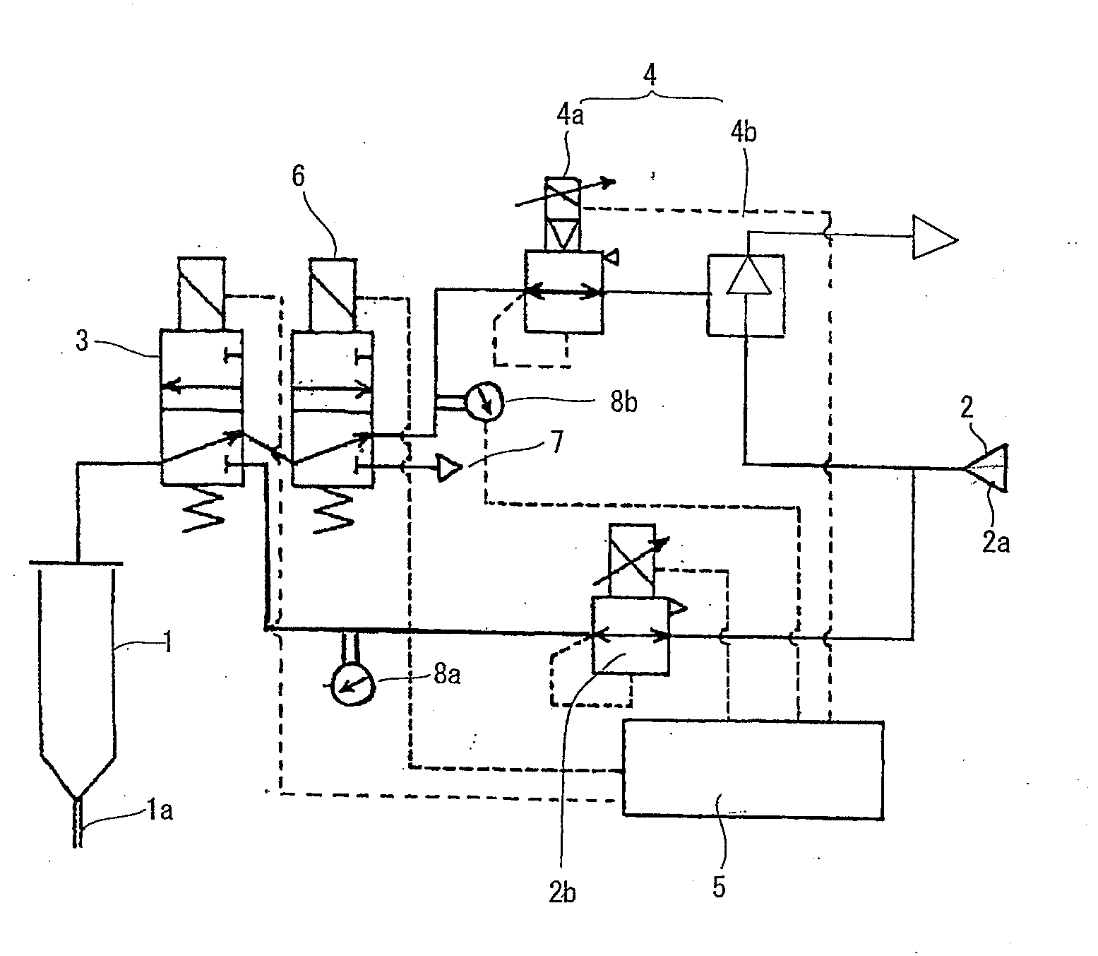
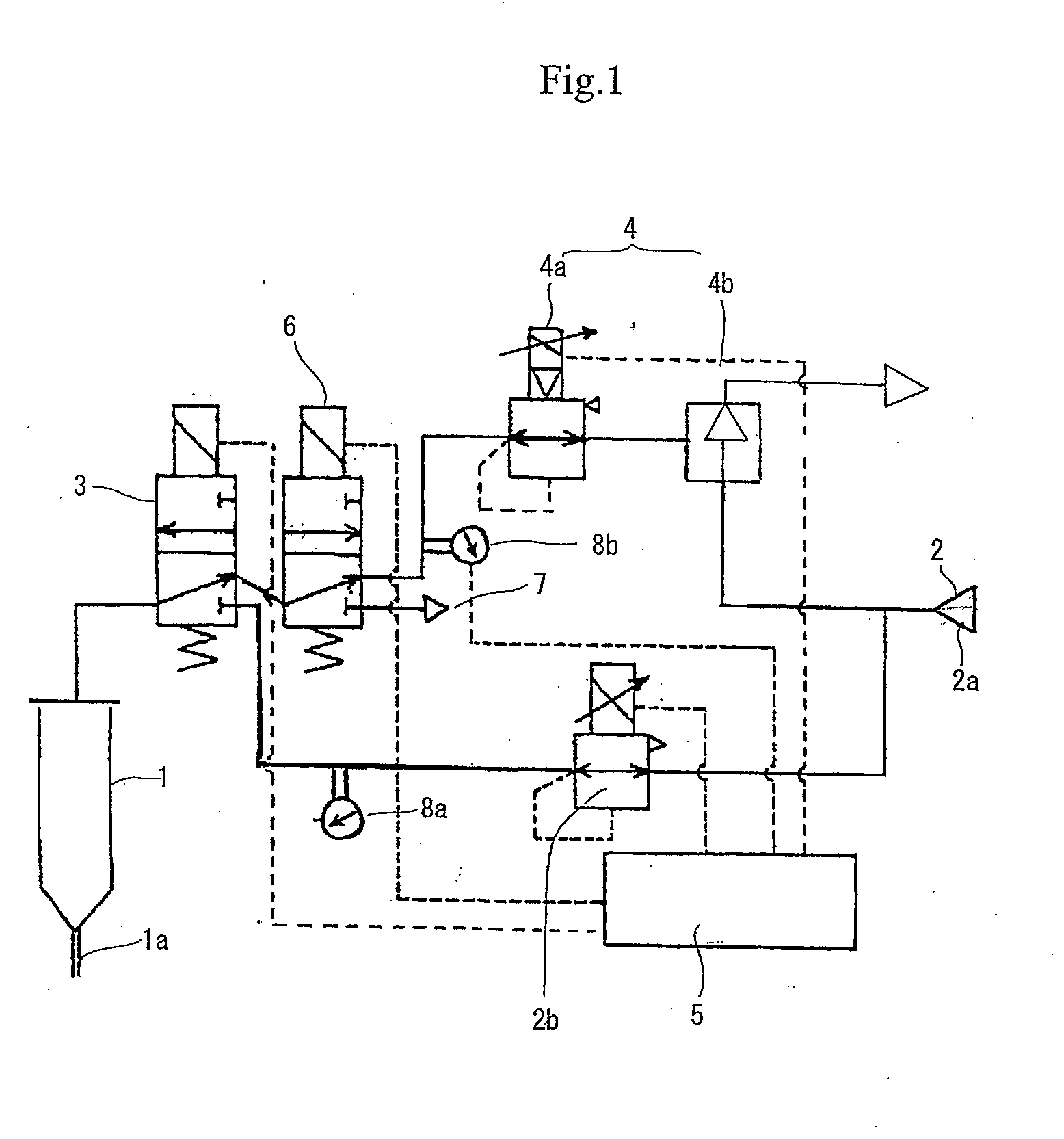
[0013] Note that in FIG. 1, solid and broken lines indicate a pressure circuit and a signal circuit, respectively.

[0014] As shown, a syringe 1 to dispense a liquid filled therein is connected at one end thereof via a two-position delivery valve 3 to a pressurized gas source 2 including a compressor 2a and pressure regulator 2b provided downstream of the compressor 2a as shown and which supplies a liquid dispensing pressure. The syringe 1 has a nozzle 1a provided at the other end thereof. A negative pressure source 4 including a negative-pressure electropneumatic regulator 4a and an ejector 4b provided upstream of the electropneumatic regulator 4a as shown and which supplies a liquid retaining negative pressure into the syringe 1 is connected to the delivery valve 3 via a two-position valve 6 openable to the atmosphere.

[0015] Namely, the delivery valve 3 communicating with the syringe 1 is switched in position to communicate with either the pressuring gas source 2 or negative press...


PUM


Abstract

A liquid dispenser is provided which dispenses a predetermined amount of a liquid from a reservoir. It includes a negative pressure system to supply a negative pressure which acts on the liquid in the liquid reservoir while no liquid is being dispensed. The negative pressure system includes a negative pressure source, an electropneumatic regulator communicating with the negative pressure source to regulate the pressure inside the liquid reservoir to a desired negative pressure level, a pressure sensor provided between the electropneumatic regulator and reservoir, and a control means for controlling the electropneumatic regulator responsive to a signal from the pressure sensor to regulate the pressure inside the reservoir to the desired negative pressure level. It can assure a negative pressure which is stable even just after it is switched on and can thus work stably even right after the switch-on.

Description

FIELD OF THE INVENTION [0001] The present invention generally relates to a dispenser capable of dispensing a paste- or cream-state electronic material, adhesive and other middle- or high-viscosity liquid material, liquid material varying in viscosity with time, low-viscosity liquid material or the like accurately from a syringe, and more particularly, to a liquid dispenser capable of a high-accuracy dispensing even right after it is turned on. BACKGROUND ART [0002] One of the liquid dispensers of the above type is known from, for example, the Japanese Unexamined Patent Publication No. 217271 of 1990. [0003] The above Unexamined Japanese Patent Publication discloses a liquid dispenser having connected thereto a syringe and an air source and air aspirator via a dispensing solenoid valve and which includes an accumulator and pressure-regulation reducing valve provided in this order between the dispensing solenoid valve and air source upstream of the solenoid valve, an accumulator and s...

Claims


Application Information

Patent Timeline
IPC IPC(8): G01F19/00B67D7/72
CPCB05C5/0225B05C17/002B05C11/1002G01F11/023G01F11/029G01F13/00B05C5/00B05C11/10
Inventor IKUSHIMA, KAZUMASA
Owner MUSASHI ENG INC
Why Eureka
Try Eureka