
Surface mount adhesive, mounting structure including the same, and method for producing mounting structure

a technology of mounting structure and adhesive, which is applied in the direction of adhesive types, printed circuit aspects, final product manufacturing, etc., can solve the problems of increasing the price of electronic components, and increasing the price of circuit boards, etc., and achieves stable dispensing

Inactive Publication Date: 2013-07-09
PANASONIC CORP
View PDF9 Cites 0 Cited by
  • Summary
  • Abstract
  • Description
  • Claims
  • Application Information

AI Technical Summary

Benefits of technology

The invention aims to solve problems with dispensing surface mount adhesive by adding a high-specific gravity and hardness second filler to the adhesive. This increases the adhesive's specific gravity, leading to more stable dispensing and reduced splashing and tailing. When dispensing to circuit boards, this method also reduces failures and stabilizes the amount of adhesive applied. Additionally, the adhesive's adhesion to the nozzle is suppressed, resulting in a more stable dispensing process.

Problems solved by technology

This has lead to higher packing density of electronic components and rising prices per electronic component.
Further, due to increased added value per circuit board with electronic components mounted thereon, prices per circuit board also tend to rise.
Since the air method utilizes only air pressure to control the amount of a surface mount adhesive applied, the applied amount tends to vary and become unstable with a decrease of the amount of the surface mount adhesive inside the syringe.
Since the dispensing of a surface mount adhesive is conducted at a high speed cycle of approximately 0.07 s / shot, the following dispensing failures may occur unless the physical properties of the filler are optimized.
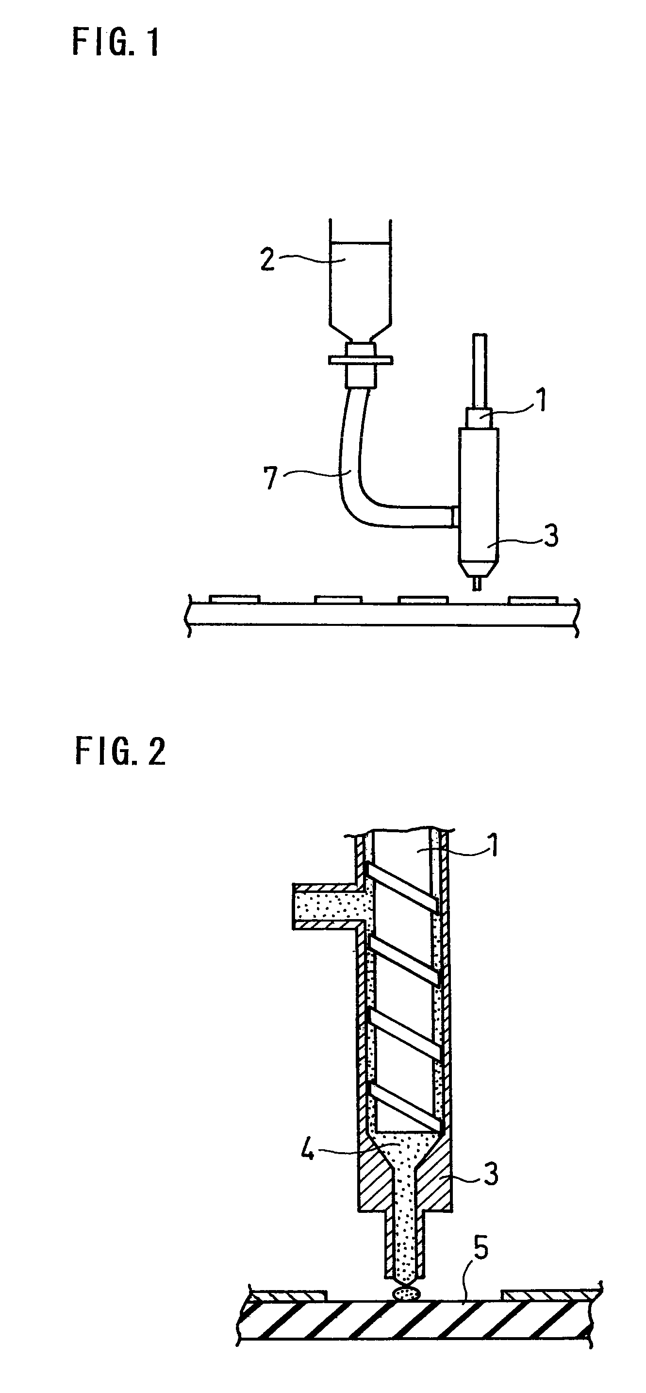
First, when a nozzle is brought into contact with a circuit board to dispense a surface mount adhesive to the circuit board, the nozzle is pressed against the circuit board, and thus part of the surface mount adhesive being dispensed may splash due to pressure.
Second, if the surface mount adhesive is not smoothly dropped on the circuit board, the surface mount adhesive may splash or tail (string) when the nozzle moves from one position to another to dispense the surface mount adhesive.
Third, if the wettability of the surface mount adhesive relative to the nozzle is insufficient, the surface mount adhesive may adhere or stick to the nozzle if it is continuously dispensed.
This may cause the applied amount to become unstable or cause a nozzle clogging.

Method used


Image

  • Surface mount adhesive, mounting structure including the same, and method for producing mounting structure
  • Surface mount adhesive, mounting structure including the same, and method for producing mounting structure
  • Surface mount adhesive, mounting structure including the same, and method for producing mounting structure

Examples


examples

[0060]The invention is hereinafter described specifically by way of Examples and Comparative Examples.

[0061]Using the following components, the surface mount adhesives of Examples and Comparative Examples were prepared.

[0062]1. Base resin: XBM5000 of AJINOMOTO CO., INC. containing a liquid epoxy resin, a curing agent and an accelerator[0063]Liquid epoxy resin: bisphenol A / F mixed resin[0064]Curing agent: amine-type[0065]Accelerator: imidazole-type

[0066]2. First filler: talc

[0067]3. Second filler: alumina, silica gel, zircon, or silicon carbide

[0068]The characteristics of the respective fillers are shown in Table 1.

[0069]

TABLE 1LargestparticlesizeSpecificRevised Mohs(μm)gravityhardnessTalc102.71Alumina0.1 to 1503.912Silica gelZircon804.77.5Silicon carbide903.213

[0070]The base resin XBM5000 was fully mixed with the first filler and the second filler, and the mixture was defoamed to prepare a surface mount adhesive.

[0071]The first filler used was talc, which is relatively inexpensive....


PUM

PropertyMeasurementUnit
glass transition pointaaaaaaaaaa
mean particle sizeaaaaaaaaaa

Abstract

A surface mount adhesive includes an epoxy resin, a curing agent, an accelerator, a first filler, and a second filler. The second filler has a specific gravity 1.1 to 3 times that of the first filler, and the second filler has a hardness higher than that of the first filler. The first filler has a largest particle size of 1 to 100 μm, and the second filler has a largest particle size of 1 to 100 μm, a specific gravity of 1.7 to 4.5, and a revised Mohs hardness of 2 to 12. The weight ratio of the first filler to the second filler is from 1:3 to 3:1, and the surface mount adhesive has a specific gravity of 1.2 to 1.5. When the surface mount adhesive is dispensed, dispensing failures are suppressed, and dispensing stability is improved.

Description

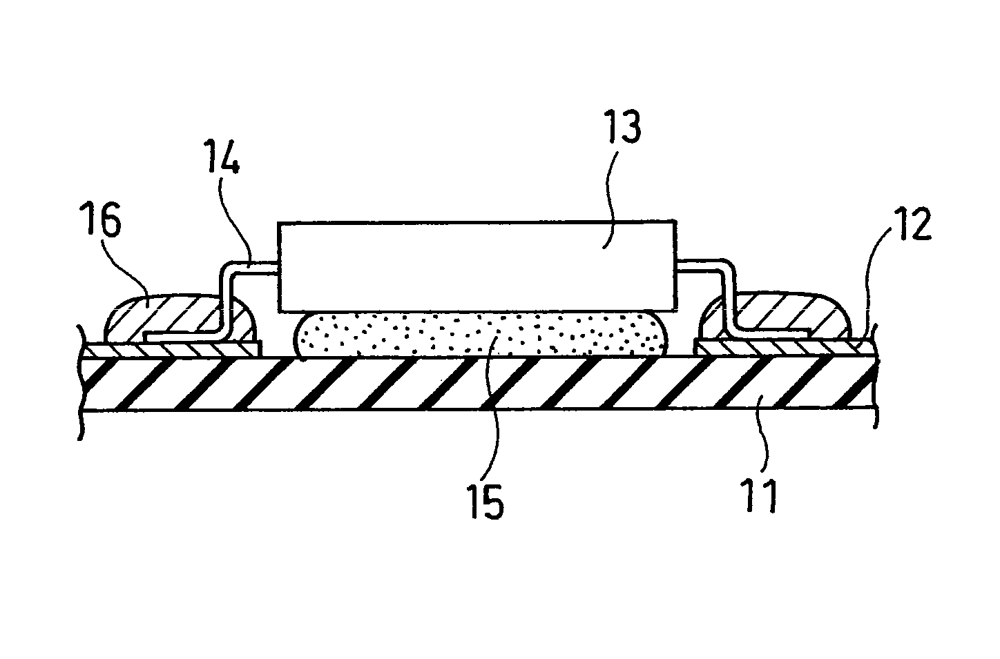
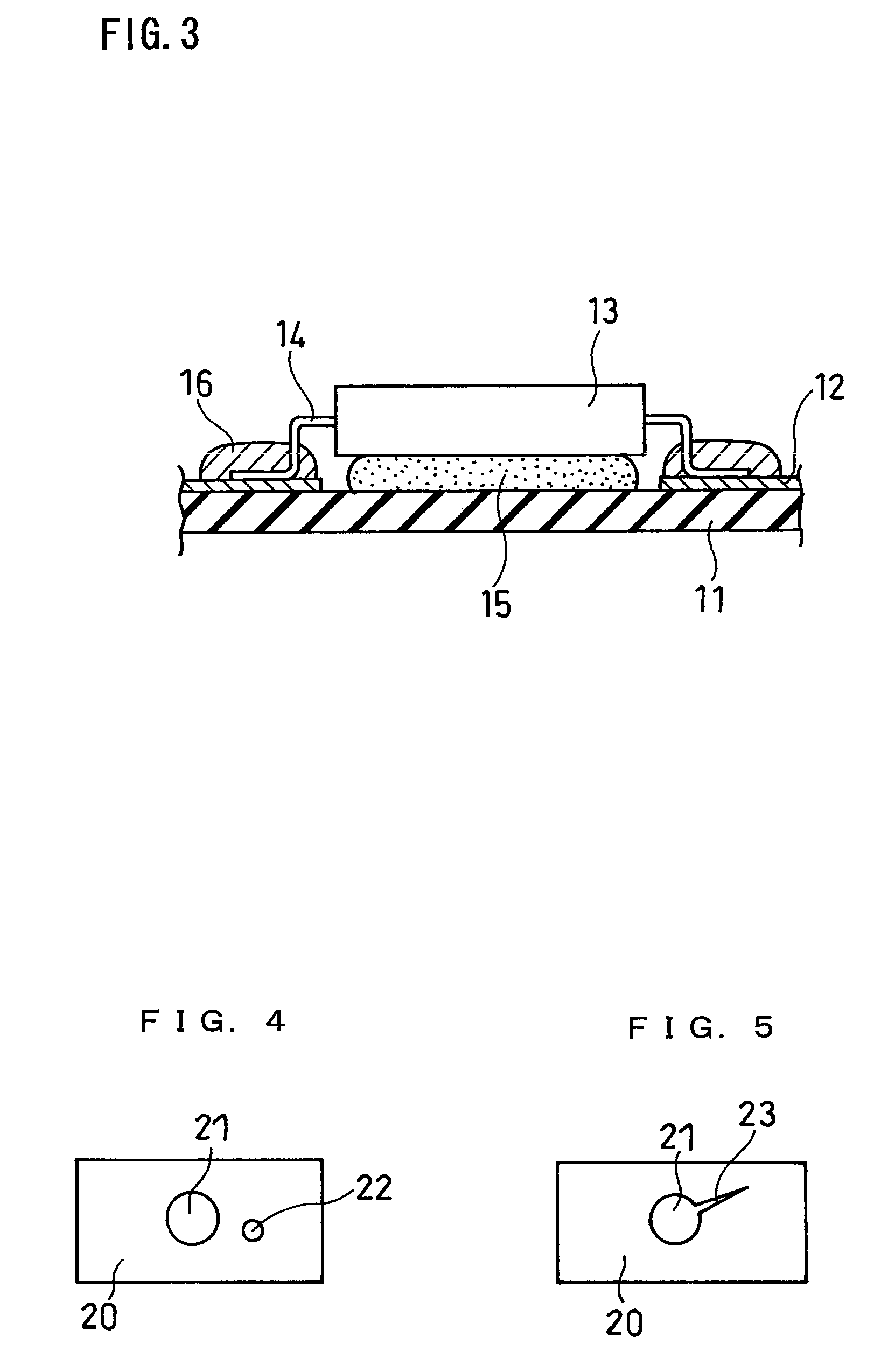
FIELD OF THE INVENTION[0001]The invention relates to a surface mount adhesive used to fix electronic components to circuit boards for electric products, a mounting structure using the surface mount adhesive, and a method for producing a mounting structure.BACKGROUND OF THE INVENTION[0002]With the recent trend of electronic devices toward higher performance, circuit boards have been required to be thinner, and electronic components have been required to be mounted more densely. To meet such requirements, electronic components such as chip components, CSPs (chip size packages), and ICs have been designed to be smaller and provide higher performance, and circuit boards have been provided with narrow pitch wiring to achieve micro wiring. This has lead to higher packing density of electronic components and rising prices per electronic component. Further, due to increased added value per circuit board with electronic components mounted thereon, prices per circuit board also tend to rise.[...

Claims


Application Information

Patent Timeline
Patent Type & Authority Patents(United States)
IPC IPC(8): C04B26/06C08K3/34C08K3/10C08J3/22H05K1/02
CPCC09J163/00H05K3/305C08K3/34H05K2201/10689H05K2201/0209H05K2201/0266Y02P70/50
Inventor KUWABARA, RYOYAMAGUCHI, ATSUSHIMIYAKAWA, HIDENORI
Owner PANASONIC CORP
Learn More