Capacitance sensing circuit

a capacitive sensing and circuit technology, applied in the direction of fluid pressure measurement, fluid pressure measurement by electric/magnetic elements, instruments, etc., can solve the problems of signal-to-noise ratio degraded and noise becomes a significant part of total error in sensor outpu

Active Publication Date: 2007-10-04
ROSEMOUNT INC
View PDF15 Cites 20 Cited by
  • Summary
  • Abstract
  • Description
  • Claims
  • Application Information

AI Technical Summary

Benefits of technology

[0006]The circuit comprises a control circuit. The control circuit controls the baseband envelope of the modulated potentials as a function of the detector output. The control circuit provides a process variable output in the baseband frequency range.
[0007]In one embodiment, the sensing capacitance varies

Problems solved by technology

Signal-to-noise ratios are degraded, and noise becomes

Method used


Image

  • Capacitance sensing circuit
  • Capacitance sensing circuit
  • Capacitance sensing circuit

Examples


Embodiment Construction

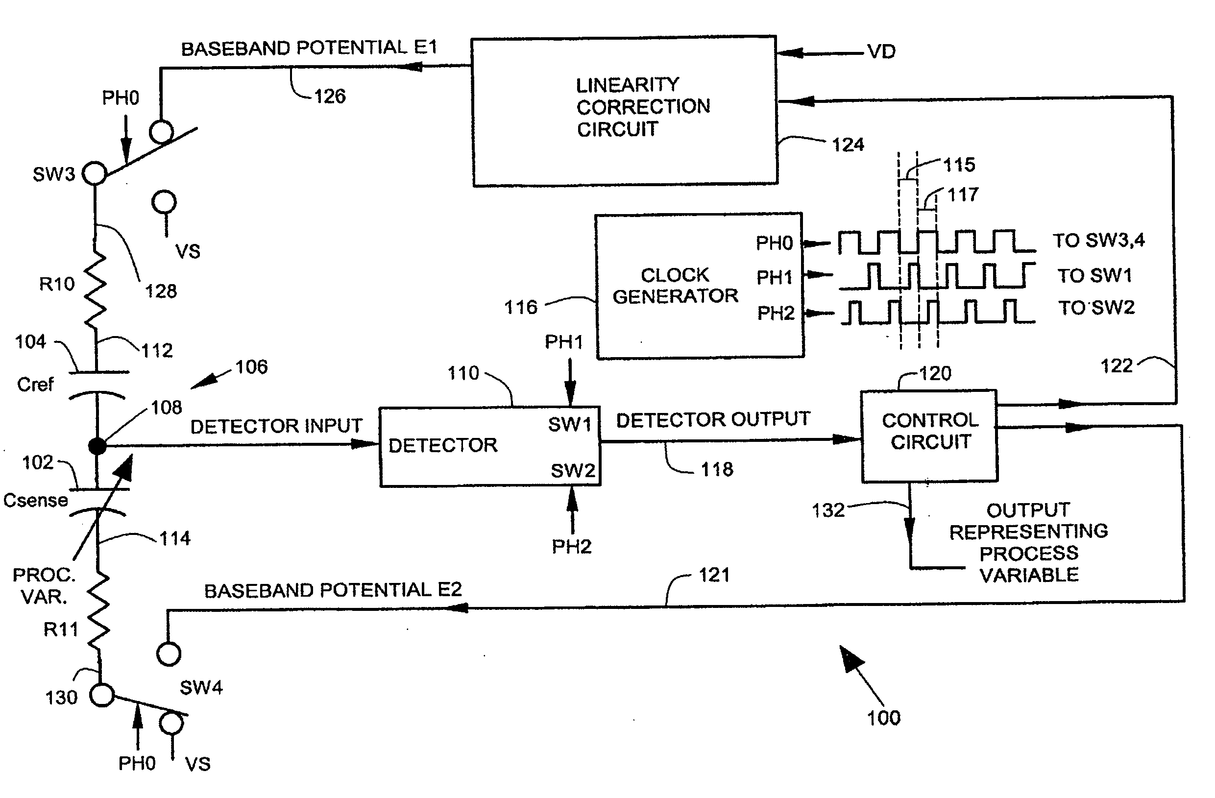
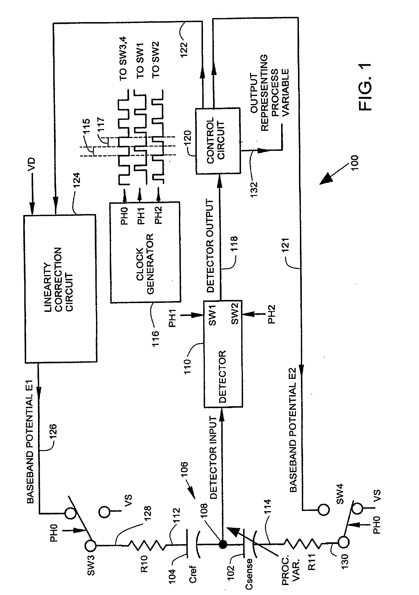
[0019]In the embodiments described below, a process variable sensing circuit senses a process variable capacitively. The process variable sensing circuit comprises a sensing capacitor and a reference capacitor connected in series to form a capacitive voltage divider. The sensing capacitor senses variations in a process variable at baseband frequencies. The ends of the capacitive voltage divider receive modulated potentials that are modulated at a carrier frequency. The connection between the sensing capacitor and the reference capacitor provides a detector input. A detector circuit detects the detector input and provides a detector output. The detector circuit operates in a carrier frequency band and provides a detector output that is demodulated. A control circuit controls the amplitudes of the modulated potentials as a function of the detector output. The control circuit provides a process variable output at baseband frequencies.

[0020]The low level detector input is free of switch...


PUM


Abstract

A circuit that senses a process variable, comprises a voltage divider that includes first and second capacitances. At least one of the capacitances is varied by the process variable. Divider ends receive modulated potentials, and a divider center tap coupled to a detector. The detector has a detector output representing carrier frequency range components. A control circuit controls a baseband envelope of the modulated potentials as a function of the detector output.

Description

CROSS-REFERENCE TO RELATED APPLICATION[0001]The present application is based on and claims the benefit of U.S. provisional patent application Ser. No. 60 / 786,984, filed Mar. 29, 2006, the content of which is hereby incorporated by reference in its entirety.BACKGROUND OF THE INVENTION[0002]This invention relates to capacitive sensing circuit for process variables. As microstructure fabrication processes improve, capacitive sensors of process variables can be made in increasingly smaller sizes to reduce size and cost of products that include such capacitive sensors. As the size of capacitive sensors decrease, the rest capacitance is becoming increasingly smaller as well. Capacitive sensors with rest capacitances of about 15 pF, for example, can be constructed in layered sapphire structures, and without the use of dielectric oil to increase capacitance. With such small rest capacitances, stray capacitances that couple noise into the capacitive sensor become larger with respect to the r...

Claims


Application Information

Patent Timeline
IPC IPC(8): G01L9/12G01R27/26
CPCG01D5/24G01D3/028
Inventor KLEVEN, LOWELL A.
Owner ROSEMOUNT INC
Why Eureka
Try Eureka