Water-cooled internal combustion engine

a technology of internal combustion engine and water jacket, which is applied in the direction of machines/engines, mechanical equipment, cylinders, etc., can solve the problems of increasing the manufacturing cost of the cylinder head, the uniformity of temperature distribution in the cylinder head is worsened, and the cooling effect of the cooling water flowing through the water jacket is difficult to be smooth, so as to facilitate the support of the core, reduce the cooling effect of the cooling water flowing through the water jacket, and reduce the manufacturing cos

Active Publication Date: 2007-10-04
HONDA MOTOR CO LTD
View PDF7 Cites 21 Cited by
  • Summary
  • Abstract
  • Description
  • Claims
  • Application Information

AI Technical Summary

Benefits of technology

[0010]The flow restricting means dividing the exhaust passage water jacket into the upstream and the downstream water jacket forces the cooling water into the combustion chamber water jacket. Therefore, the amount of the cooling water used for cooling the combustion chamber walls is large as compared with that can be used for the same purpose when the flow restricting means is used and hence the combustion chamber walls can be effectively cooled by the sufficient cooling water. An exhaust passage wall forming the exhaust manifold passage is cooled by the cooling water flowing through the exhaust passage water jacket on the upstream side of the combustion chamber water jacket. The exhaust passage walls are cooled by the cooling water flowing through the exhaust passage water jacket, and the combustion chamber walls are cooled effectively by a large quantity of the cooling water. Consequently, the uniformity of temperature distribution in the combustion chamber walls and the exhaust passage walls can be improved and the uniformity of temperature distribution in the cylinder head is improved.
[0029]The through hole formed to facilitate supporting the core for forming the exhaust manifold passage is used for receiving a measuring device or a tubular member. Therefore, any additional through hole specially for receiving the measuring device or the tubular member is not necessary. Since the through hole does not extend through the water jacket, the area of a part of the exhaust manifold passage surrounded by the water jacket is not decreased by the through hole for receiving the detecting device or the tubular member. Thus any additional through hole is not formed, the cylinder head can be manufactured at a low manufacturing cost, and the reduction of the cooling effect of the cooling water flowing through the water jacket can be prevented.

Problems solved by technology

Thus the cooling water has difficulty in smoothly flowing through the combustion chamber water jacket as compared with flowing through the exhaust passage water jacket having a comparatively simple arrangement of passages.
Therefore, if the combustion chamber water jacket and the exhaust passage water jacket are connected simply, the respective temperatures of the combustion chamber walls and the exhaust passage walls are likely to differ from each other and the uniformity of temperature distribution in the cylinder head is worsened.
The mold and cores having such an intricate shape increases the manufacturing cost of the cylinder head.

Method used


Image

  • Water-cooled internal combustion engine
  • Water-cooled internal combustion engine
  • Water-cooled internal combustion engine

Examples


Embodiment Construction

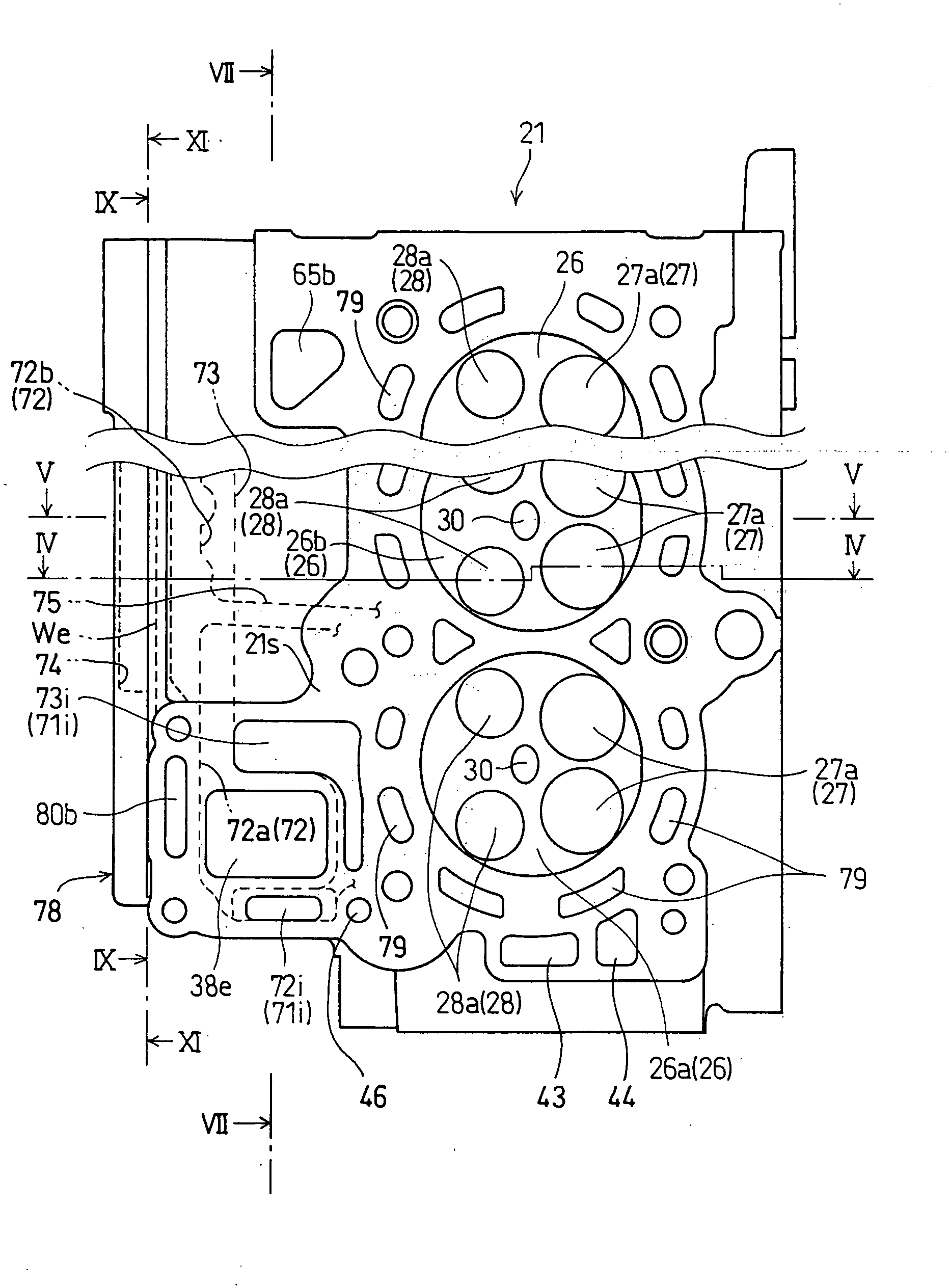
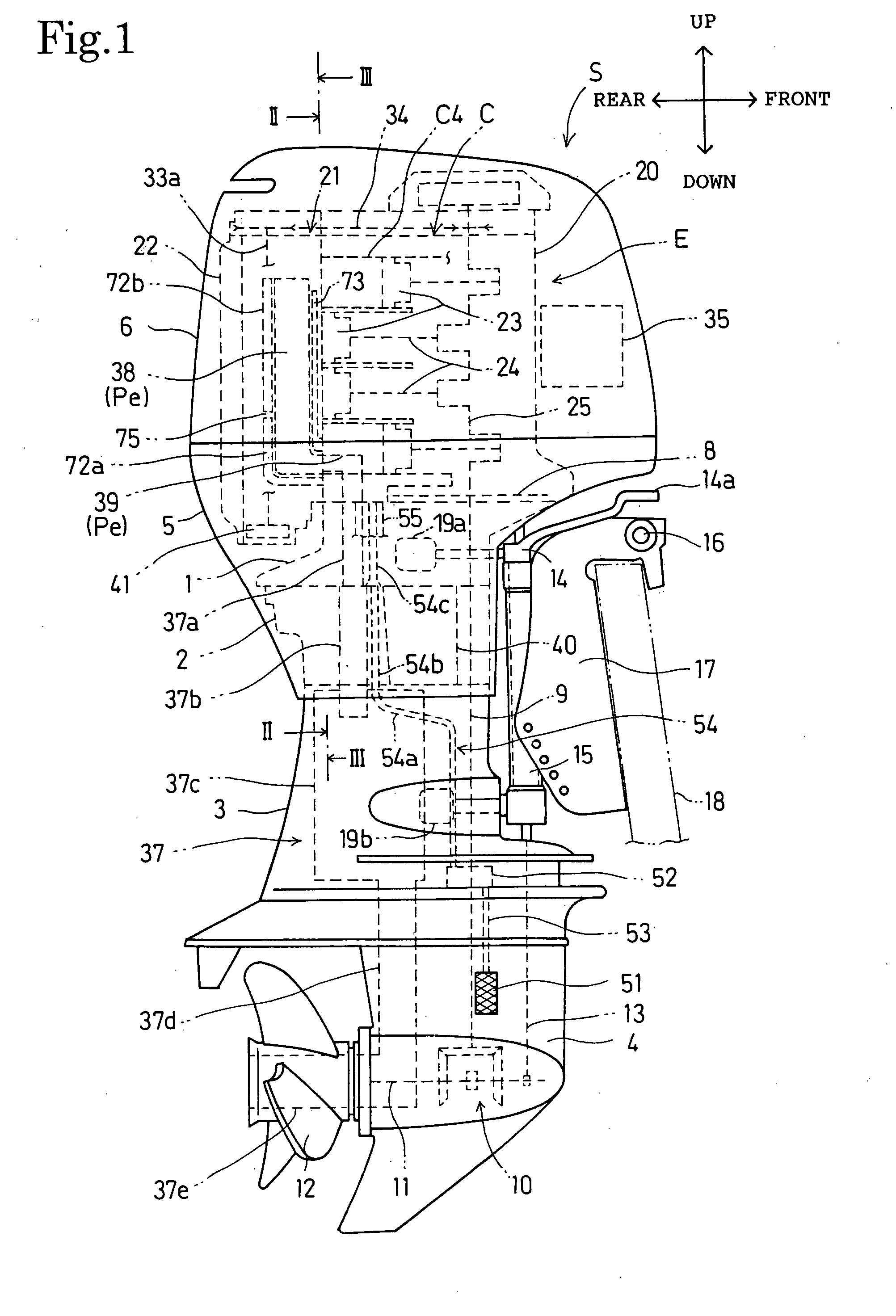
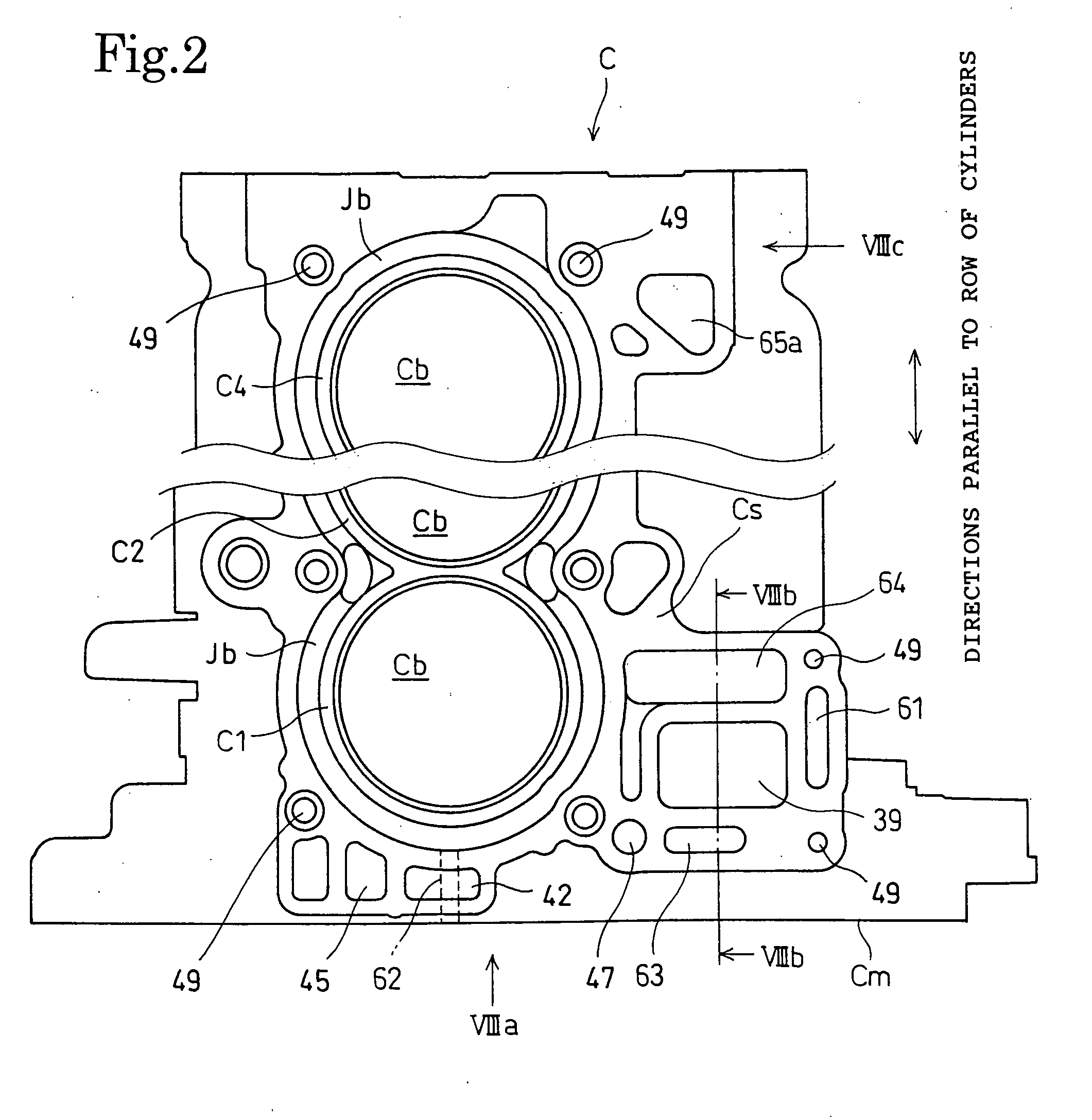
[0047]A water-cooled internal combustion engine E in a preferred embodiment of the present invention will be described with reference to FIGS. 1 to 12.

[0048]Referring to FIG. 1, the water-cooled internal combustion engine E is incorporated into an outboard motor S, namely, a marine propulsion device. The outboard motor S includes the water-cooled internal combustion engine E, namely, a vertical engine, provided with a vertical crankshaft 25. The water-cooled internal combustion engine E has a mount case 1 having an upper end joined to the water-cooled internal combustion engine E and a lower end, an oil case 2 joined to the lower end of the mount case 1, an extension case 3 connected by the oil case 2 to the mount case 1, a gear case 4 joined to the lower end of the extension case 3, a vertically extending under cover 5 surrounding a lower part of the water-cooled internal combustion engine E, the mount case 1, the oil case 2 and an upper part of the extension case 3, and an engine ...


PUM


Abstract

A water-cooled internal combustion engine has a cylinder head 21 provided with a cylinder head water jacket Jh through which cooling water flows. The cylinder head water jacket Jh includes a combustion chamber water jacket 70 surrounding combustion chambers 26 and an exhaust passage water jacket 71 around an exhaust manifold passage 38. The exhaust gas discharged from the combustion chambers 26 through exhaust ports 28 flows through the exhaust manifold passage. The exhaust passage water jacket 71 is divided into an upstream water jacket 72a and a downstream water jacket 72b by a partition wall 75. The cooling water flows from both the upstream water jacket 72a and the downstream water jacket 72a into the combustion chamber water jacket 70. Equality in temperature between a combustion chamber wall and an exhaust passage wall is improved and the cylinder head 21 is heated in a uniform temperature distribution.

Description

BACKGROUND OF THE INVENTION[0001]1. Field of the Invention[0002]The present invention relates to a water-cooled internal combustion engine cooled by circulating cooling water. More specifically, the invention relates to a structure forming water jackets in the cylinder head of a water-cooled internal combustion engine to be applied to, for example, an outboard motor.[0003]2. Description of the Related Art[0004]The cylinder head of a known water-cooled internal combustion engine disclosed in, for example, JP-A 2000-159190 is provided with an exhaust manifold passage through which the exhaust gas discharged from a plurality of combustion chambers flows, and water jackets including a combustion chamber water jacket surrounding combustion chambers and an exhaust passage water jacket surrounding the exhaust manifold passage.[0005]When the exhaust manifold passage is formed in the cylinder head, it is preferable, in view of improving the durability of the cylinder head, to reduce differen...

Claims


Application Information

Patent Timeline
Patent Type & Authority Applications(United States)
IPC IPC(8): F01P1/06F02B75/18F02F1/40F01N7/06F01N13/06
CPCF01P2060/16F01P3/202F02F1/243
Inventor TSUBOUCHI, MASANORISUZUKI, NOBUO
Owner HONDA MOTOR CO LTD
Why Eureka
Try Eureka