Sensor objective

Inactive Publication Date: 2007-10-04
ROBERT BOSCH GMBH
View PDF2 Cites 1 Cited by
  • Summary
  • Abstract
  • Description
  • Claims
  • Application Information

AI Technical Summary

Benefits of technology

[0014] The object of the present invention relating to the method is achieved in that the optical components of the deflection element are displaced and/or rotated in relation to one another to set the deflection angle, the deflection angle being monitored by measurement, and the optical components are fixed after the desired deflection angle is reached. A particular combination of optical components allows a specific setting range of the defle

Problems solved by technology

Spherical interfaces are complex to manufacture, but allow simple and precise

Method used


Image

  • Sensor objective
  • Sensor objective
  • Sensor objective

Examples


Example

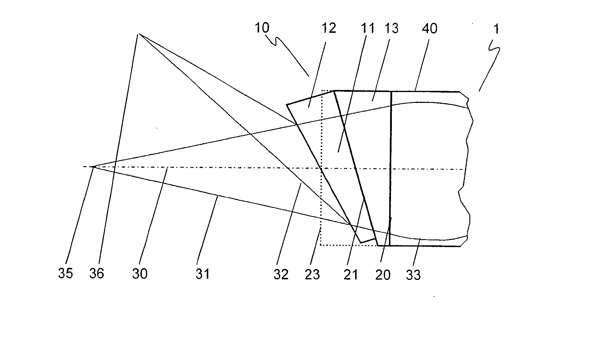
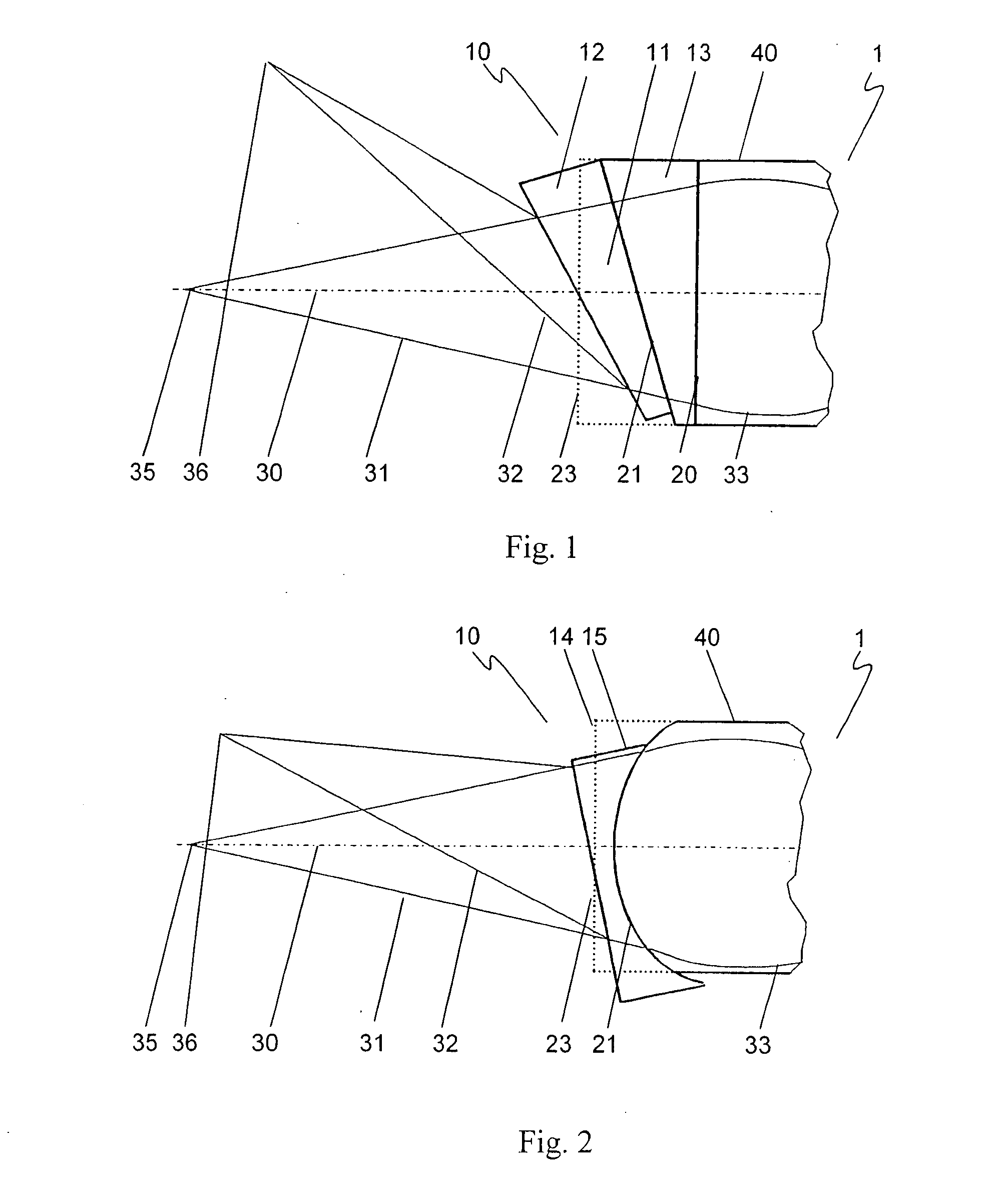
[0019]FIG. 1 shows a sensor objective 1 of an interferometric measuring device having a focusing element 40 and a deflection element 10 connected thereto. Focusing element 40 is implemented as a gradient index lens (GRIN). Deflection element 10 is composed of a first wedge-shaped component 13, which adjoins focusing element 40 at an interface 20, and a second wedge-shaped component 11, which adjoins first wedge-shaped component 13 at a planar interface 21. In this position of second wedge-shaped component 11, an incoming beam 33 incident parallel to a system longitudinal axis 30 exits from deflection element 10 at an exit surface 23 perpendicular to system longitudinal axis 30 and is relayed as an undeflected beam 31. The radiation is reflected by a surface of a measured object situated at a focal point 35 of undeflected beam 31 and fed along a reverse beam path into sensor objective 1 of an analysis unit of the interferometric measuring device (not shown).

[0020] The deflection ang...


PUM


Abstract

A sensor objective at the exit of a measuring branch of a measuring probe of an interferometric measuring unit for detecting the shape, roughness or distance of the surface of a measured object, the interferometric measuring unit including a modulation interferometer and the measuring probe being optically connected to the modulation interferometer via an optical fiber system and the sensor objective having a focusing element and a downstream deflection element for coupling out and coupling back in a measuring beam directed toward the surface to be measured and reflected from the latter. The deflection element includes at least two optical components, each having a shared interface, the deflection angle of the at least one beam deflected to a system longitudinal axis being settable by mutual displacement and/or rotation of the optical components during mounting. The mutual displacement and/or rotation of the optical components is/are performed at the shared interface(s). Therefore, arbitrary deflection angles for the beam may be set using a small number of optical components which are tailored to one another. Because no components have to be manufactured for specific customers, there is a significant reduction in manufacturing costs as well as significantly shortened manufacturing and therefore delivery times. Because the interfaces of the optical components are joined to one another without a wedge-shaped gap during the gluing of the components after adjustment, the disadvantageous influence of non-reproducible adhesive shrinkage is eliminated.

Description

FIELD OF THE INVENTION [0001] The present invention relates to a sensor objective at the output of a measuring branch of a measuring probe of an interferometric measuring device for detecting the shape of, roughness of, or the distance to the surface of a measured object, the interferometric measuring device including a modulation interferometer and the measuring probe being optically connected to the modulation interferometer using an optical fiber system and the sensor objective having a focusing element and a downstream deflection element for coupling out and coupling back in a measuring beam which is directed toward the surface to be measured and is reflected by the latter. Furthermore, the present invention relates to a method for manufacturing such a sensor objective. BACKGROUND INFORMATION [0002] An interferometric measuring device of the above-mentioned type is described in German Patent Application No. DE 198 19 762. The interferometric measuring device includes a modulatio...

Claims


Application Information

Patent Timeline
IPC IPC(8): G01B9/02
CPCG02B26/0883G01B9/02G01B2290/65
Inventor FRANZ, STEFANFLEISCHER, MATTHIAS
Owner ROBERT BOSCH GMBH
Why Eureka
Try Eureka