
Diffraction element, optical pickup and optical disc apparatus

Inactive Publication Date: 2007-10-04
SONY CORP
View PDF0 Cites 1 Cited by
  • Summary
  • Abstract
  • Description
  • Claims
  • Application Information

AI Technical Summary

Benefits of technology

[0007] To produce the diffraction element, injection molding process is often applied; the parts are generated by injecting optical plastics, or resins, into a mold. When using the injection molding to produce the diffraction element with fine grating and deep grooves, it is preferable to raise the resin filling rate of the mold to improve the reproducibility of the diffraction pattern or its transcription capability. However, in this case, the plastics and molds may be at high temperatures during the injection process. In addition, it is preferable to raise the temperature of the plastics to easily take the part from the mold after the injection process.
[0008] As a result, the injection-molded parts can be deformed due to high temperatures during the injection process, causing inappropriate aberration on the manufactured diffraction element. If the plastics and the molds are at lower temperatures, the diffraction element can be produced appropriately. However, that decreases the transcription capability due to lower resin filling rate, causing inappropriate aberration on the manufactured diffraction element.

Problems solved by technology

However, in this case, the plastics and molds may be at high temperatures during the injection process.
As a result, the injection-molded parts can be deformed due to high temperatures during the injection process, causing inappropriate aberration on the manufactured diffraction element.
However, that decreases the transcription capability due to lower resin filling rate, causing inappropriate aberration on the manufactured diffraction element.

Method used


Image

  • Diffraction element, optical pickup and optical disc apparatus
  • Diffraction element, optical pickup and optical disc apparatus
  • Diffraction element, optical pickup and optical disc apparatus

Examples


Embodiment Construction

[0035] An embodiment of the present invention will be described in detail with reference to the accompanying drawings.

(1) Configuration of Optical Disc Device

(1-1) Overall Configuration of Optical Disc Device

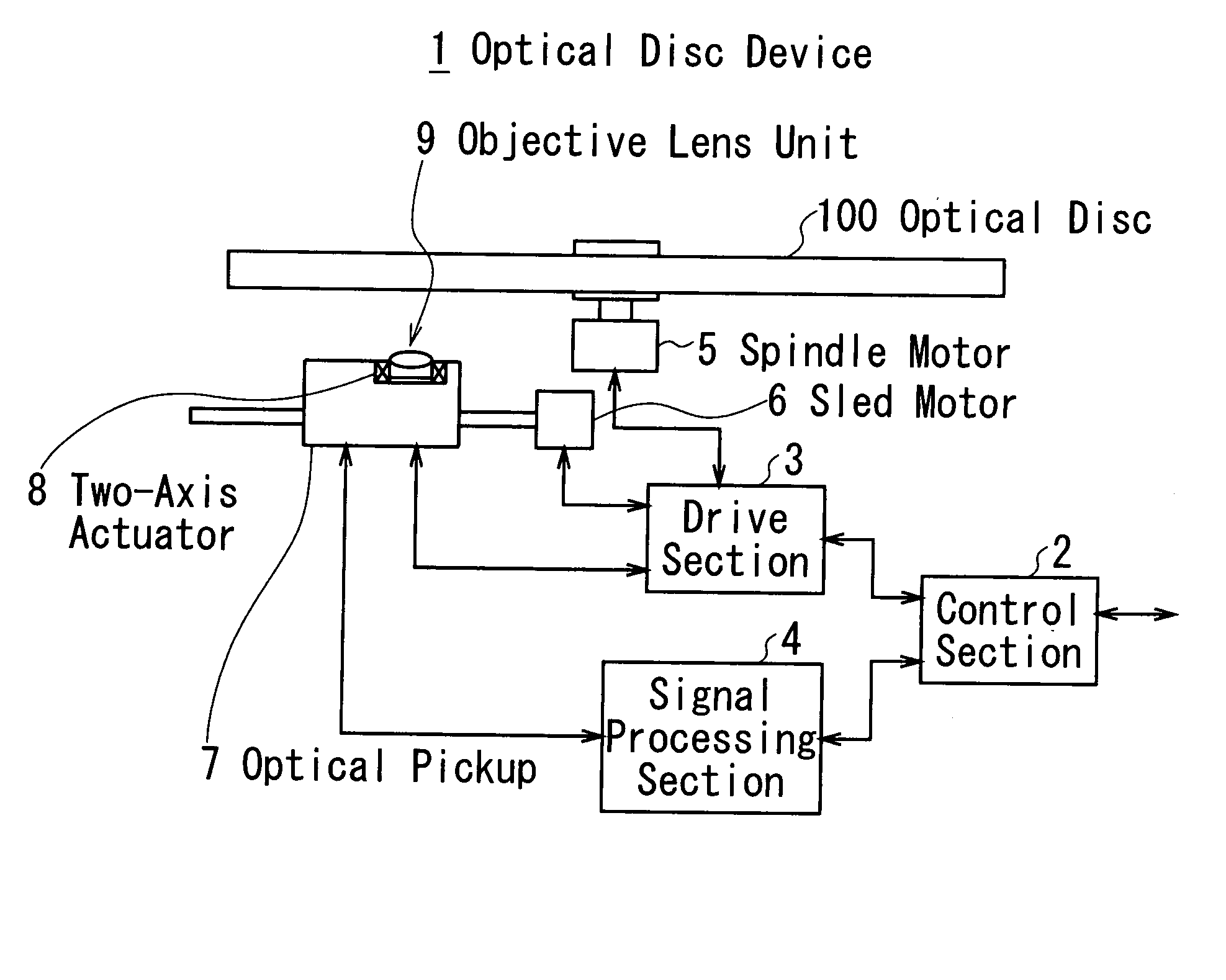
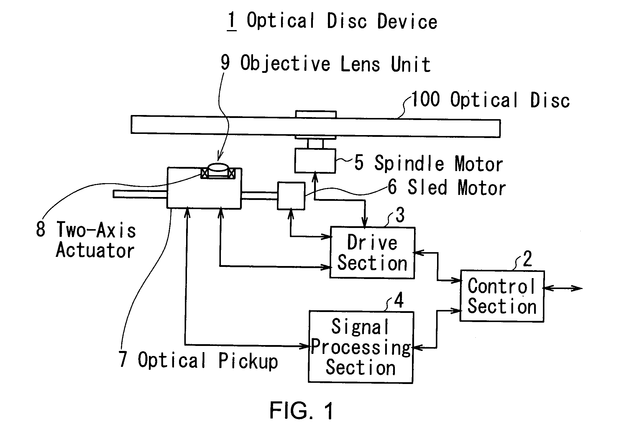
[0036] In FIG. 1, the reference numeral 1 denotes an optical disc device with a diffraction element according to an embodiment of the present invention. The optical disc device 1 reproduces signals from an optical disc 100 which is one of the following formats: Compact Disc (CD) type, Digital Versatile Disc (DVD) type or “Blu-ray Disc (Registered Trademark)” (BD) type.

[0037] A control section 2 takes overall control of the optical disc device 1. After the optical disc 100 is inserted into the optical disc device 1, the control section 2 controls, in response to a playback command or the like from external devices (not shown), a drive section 3 and a signal processing section 4 to reproduce information from the optical disc 100.

[0038] The drive section 3 under the control ...


PUM


Abstract

A diffraction element includes: an injection-molded transparent first member having two optical surfaces; and a second member firmly attached to one of the optical surfaces of the first member and provided with a first diffraction pattern on a surface, wherein the second member is a first ultraviolet curable resin having a refraction index in a range of ±0.013 with respect to a refraction index of the first member.

Description

CROSS REFERENCES TO RELATED APPLICATIONS [0001] The present invention contains subject matter related to Japanese Patent Application JP2006-317460 filed in the Japanese Patent Office on Nov. 24, 2006, the entire contents of which being incorporated herein by reference. BACKGROUND OF THE INVENTION [0002] 1. Field of the Invention [0003] The present invention relates to a diffraction element, optical pickup and optical disc apparatus, and is preferably applied to a diffraction element for various wavelengths, for example. [0004] 2. Description of the Related Art [0005] Typically, an optical disc device includes an optical pickup in which a diffraction element is installed to correct an aberration of an optical beam. The diffraction element includes a diffraction grating with fine grooves on its transparent plate base. An optical path difference between the top and bottom of the diffraction grating diffracts the optical beam (see Jpn. Pat. Laid-open Publication No. 2005-339762, for exa...

Claims


Application Information

Patent Timeline
IPC IPC(8): G02B26/08
CPCG11B7/1353G11B2007/0006G11B7/22G11B7/13922G02B5/18
Inventor SATO, JINYAMADA, TAKATOSHIKAWAKITA, SATOSHIKANNO, KYUAIBA, MOTOO
Owner SONY CORP
Learn More