
Clamp ring and disc drive having the same

a technology of disc drive and clamping ring, which is applied in the field of recorders, can solve the problems of information recording and reproducing errors, damage to at least one, and work becomes difficult, and achieve the effect of reducing undulation in the clamping ring

Inactive Publication Date: 2007-10-04
FUJITSU LTD
View PDF3 Cites 13 Cited by
  • Summary
  • Abstract
  • Description
  • Claims
  • Application Information

AI Technical Summary

Benefits of technology

[0006]Accordingly, it is an exemplary object of the present invention to provide a clamp ring and a disc drive having the same, which reduces undulation in attaching the clamp ring to a hub.
[0008]A circle that passes centers of the plural stress relaxation holes may be greater than a circle that passes centers of the plural screw holes. A position of the stress relaxation hole is more influential than a diameter and thickness of the stress relaxation hole, and the undulation reduction effect increases as the stress relaxation hole is located to the outside. In addition, this configuration gives an additional effect: When the centers of both stress relaxation holes and screw holes are arranged on the same circle, a wall becomes thin between each stress relaxation hole and each screw hole as the diameter of the stress relaxation hole increases and thus working becomes difficult. When the wall is torn down, burrs and dust or fine particles occur. The fine particles when dropping on the disc causes a collision between the head and the disc, resultant damages of at least one of them, and information recording and reproducing errors. When the circle that passes the centers of the screw holes shifts from the circle that passes the centers of the stress relaxation holes, the arrangement of the stress relaxation holes compromises with a sufficiently thick wall between the screw hole and the stress relaxation hole. Therefore, workability improves.
[0010]A clamp ring according to another aspect of the present invention that clamps a disc onto a spindle motor that rotates the disc includes an annular disc shaped body fixed onto a hub that rotates with a shaft of the spindle motor, the body arranging plural screw holes in a circumferential direction of the body, a screw that fixes the body onto the hub being inserted into each screw hole, wherein the body arranges plural stress relaxation holes between the plural screw holes so that each stress relaxation hole and each screw hole alternate in the circumferential direction of the body, each stress relaxation hole mitigating a deformation of the body in fixing the body onto the hub with the screw, an area of the stress relaxation holes being equal to or greater than an area of the screw holes in a surface of the body from which the screw is inserted into the body. This clamp ring exhibits the effects similar to those of the above clamp ring. In that case, an area of each stress relaxation hole is greater than an area of each screw hole or a gross area of the stress relaxation holes is greater than a gross area of the screw holes.

Problems solved by technology

In addition, this configuration gives an additional effect: When the centers of both stress relaxation holes and screw holes are arranged on the same circle, a wall becomes thin between each stress relaxation hole and each screw hole as the diameter of the stress relaxation hole increases and thus working becomes difficult.
The fine particles when dropping on the disc causes a collision between the head and the disc, resultant damages of at least one of them, and information recording and reproducing errors.
When the circle that passes the centers of the screw holes shifts from the circle that passes the centers of the stress relaxation holes, the arrangement of the stress relaxation holes compromises with a sufficiently thick wall between the screw hole and the stress relaxation hole.

Method used


Image

  • Clamp ring and disc drive having the same
  • Clamp ring and disc drive having the same
  • Clamp ring and disc drive having the same

Examples


Embodiment Construction

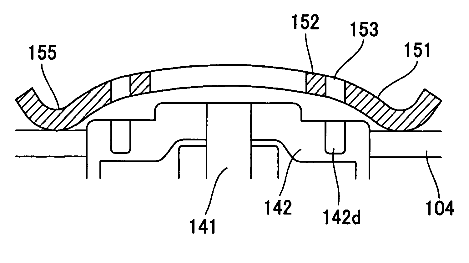
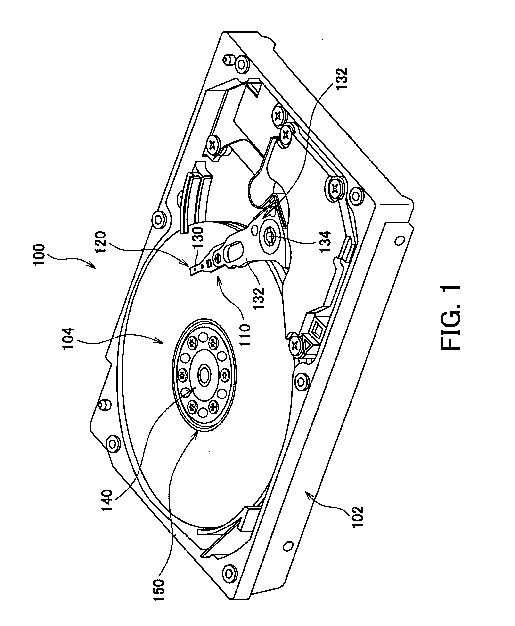
[0023]Referring now to the accompanying drawings, a description will be given of a HDD 100 according to one embodiment of the present invention. The HDD 100 includes, as shown in FIG. 1, one or more magnetic discs 104 each serving as a recording medium, a head stack assembly (“HSA”) 110, a spindle motor 140, and clamp ring 150 in a housing 102. Here, FIG. 1 is a schematic plane view of the internal structure of the HDD 100.

[0024]The housing 102 is made, for example, of aluminum die cast base and stainless steel, and has a rectangular parallelepiped shape to which a cover (not shown) that seals the internal space is jointed. The magnetic disc 104 of this embodiment has a high surface recording density, such as 100 Gb / in2 or greater. The magnetic disc 104 is mounted on a spindle of the spindle motor 140 through its center hole.

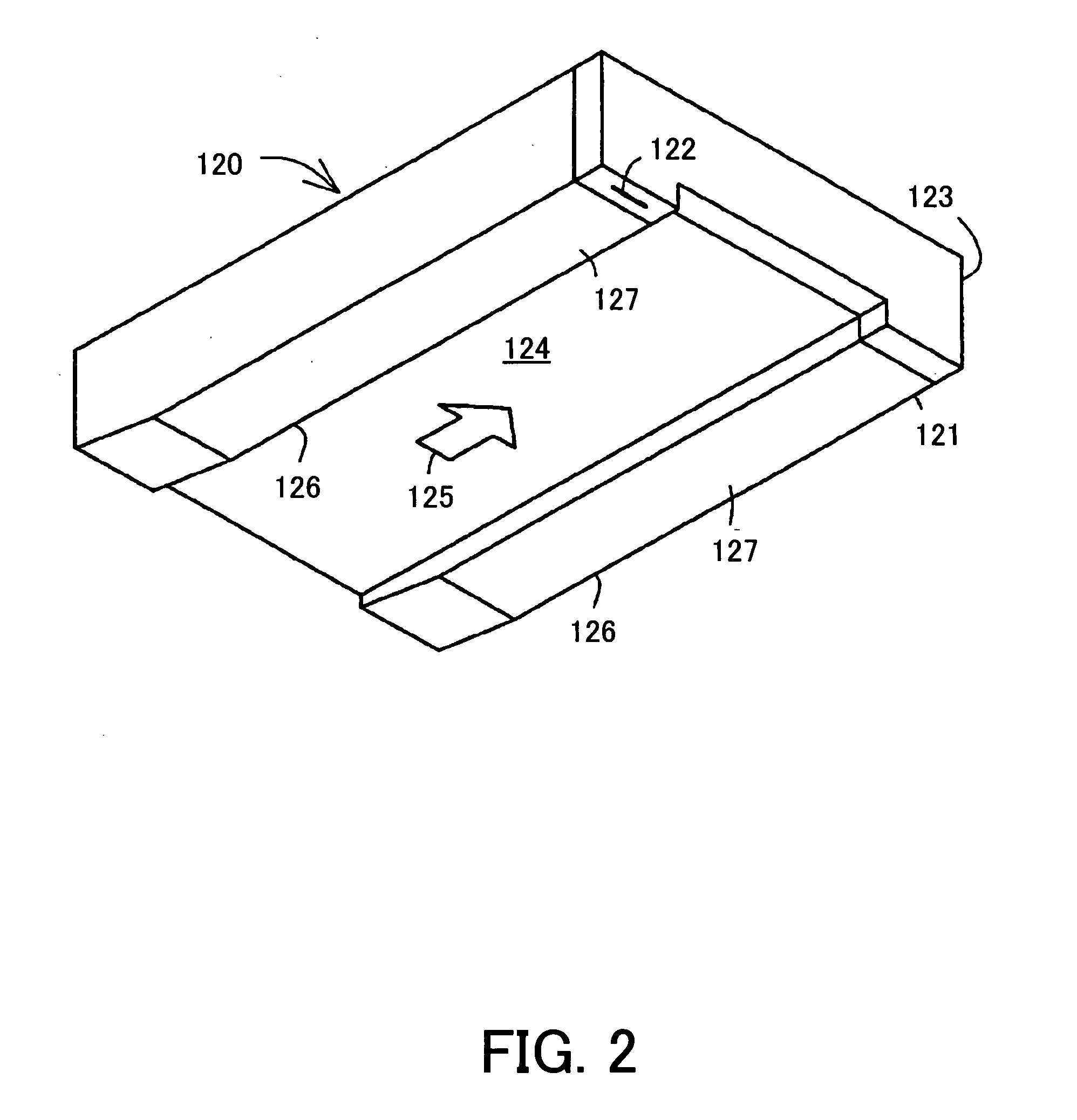
[0025]The HSA 110 includes a magnetic head part 120, a suspension 130, and a carriage 132.

[0026]The magnetic head 120 includes, as shown in FIG. 2, an approxima...


PUM

PropertyMeasurementUnit
diameteraaaaaaaaaa
diameteraaaaaaaaaa
diameteraaaaaaaaaa

Abstract

A clamp ring that clamps a disc onto a spindle motor that rotates the disc includes an annular disc shaped body fixed onto a hub that rotates with a shaft of the spindle motor, the body arranging plural screw holes in a circumferential direction of the body, a screw that fixes the body onto the hub being inserted into each screw hole, wherein the body arranges plural stress relaxation holes between the plural screw holes so that each stress relaxation hole and each screw hole alternate in the circumferential direction of the body, each stress relaxation hole mitigating a deformation of the body in fixing the body onto the hub with the screw, a diameter of the stress relaxation hole being equal to or greater than a diameter of the screw hole in a surface of the body from which the screw is inserted into the body.

Description

[0001]This application claims the right of a foreign priority based on Japanese Patent Application No. 2006-089716, filed on Mar. 29, 2006, which is hereby incorporated by reference herein in its entirety as if fully set forth herein.BACKGROUND OF THE INVENTION[0002]The present invention relates generally to a recorder, and more particularly to a clamping unit for clamping a disc or discs as a recording medium in a disc drive. The present invention is suitable, for example, for a clamp ring that fixes a disc or discs onto a spindle hub in a hard disc drive (“HDD”).[0003]Along with the recent spreads of the Internet etc., a demand for fast recording of a large amount of information is growing. A magnetic disc drive, such as an HDD, is required for a larger capacity and improved response. For the larger capacity, the HDD narrows a track pitch on the disc, and increases the number of installed discs. For the improved response, use of a faster spindle motor is promoted.[0004]Plural disc...

Claims


Application Information

Patent Timeline
Patent Type & Authority Applications(United States)
IPC IPC(8): G11B17/02
CPCG11B25/043G11B17/0287
Inventor KOIZUMI, YOSHIAKIINOKE, MISAOSUWA, MASAYASHINOMIYA, RIKAKO
Owner FUJITSU LTD
Learn More