Light-emitting diode light
- Summary
- Abstract
- Description
- Claims
- Application Information
AI Technical Summary
Benefits of technology
Problems solved by technology
Method used
Image

Examples
first embodiment
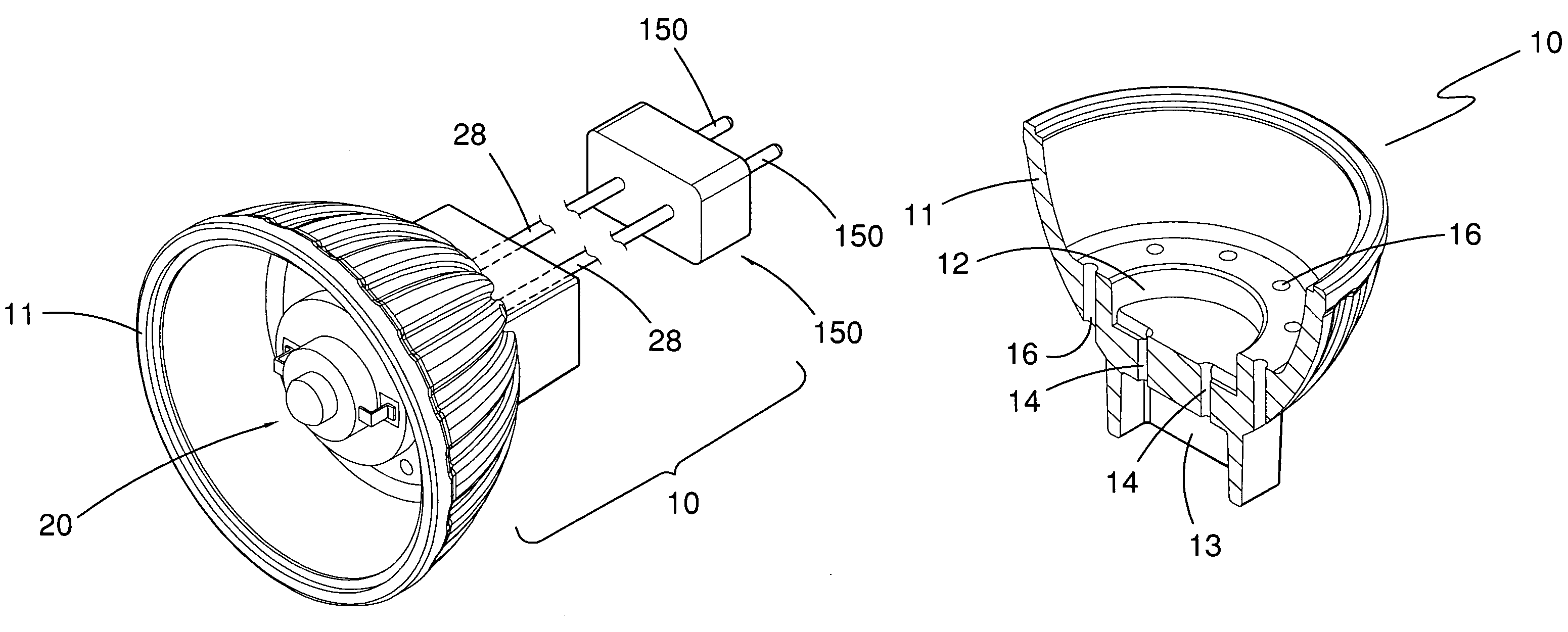
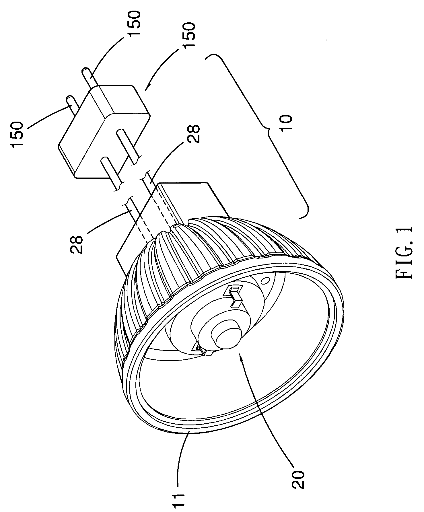
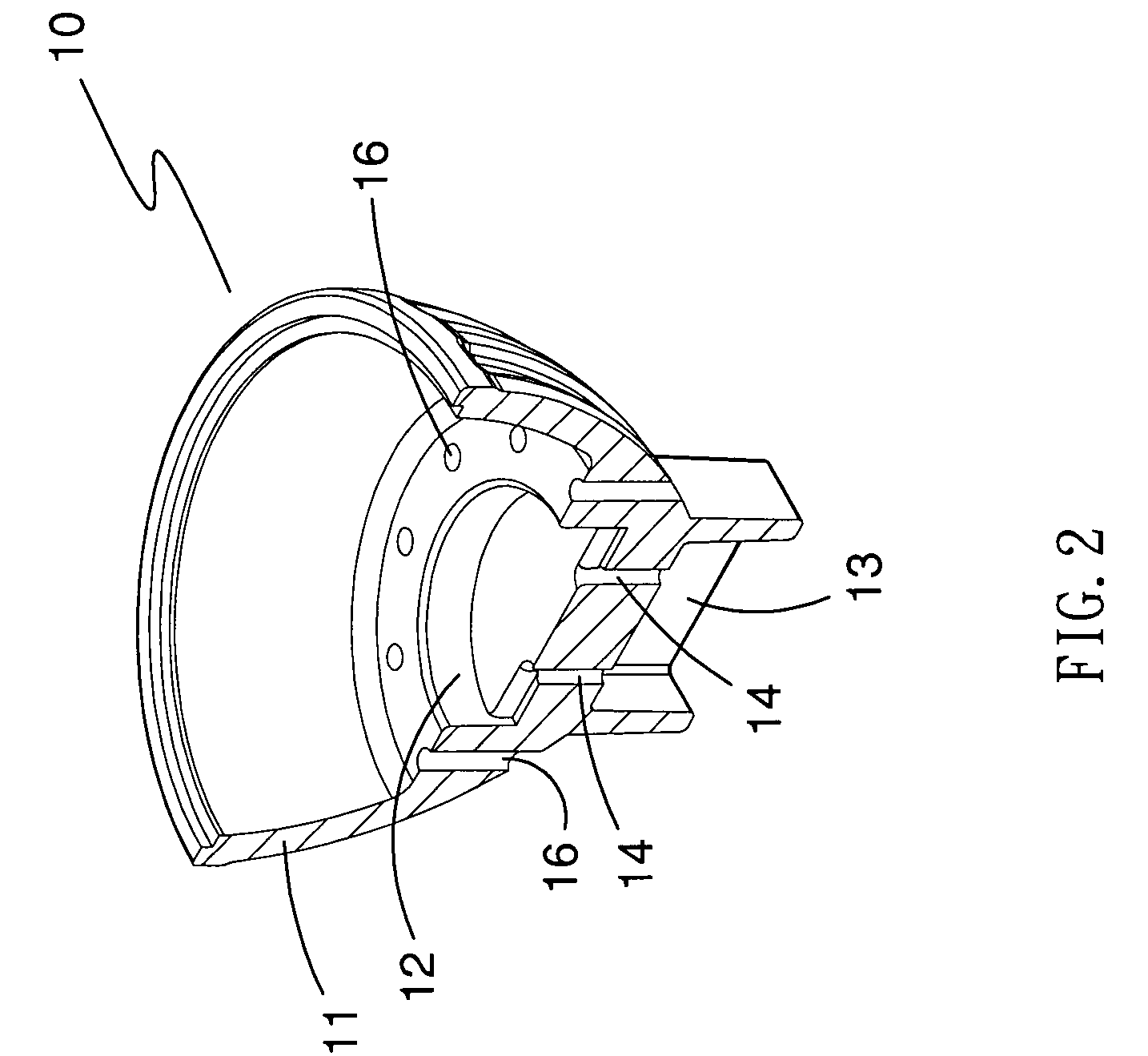
[0019]Referring to FIGS. 1 through 3, according to the present invention, an LED light 10 includes a ceramic shade 11, an illuminative unit 20, wires 28, a connector 15 and two plugs 150. In FIG. 4, the LED light 10 of the present invention further includes a reflector 17.
[0020]As shown in FIG. 2, the ceramic shade 11 is in the form of a bowl, and includes a primary chamber 12 defined therein, a secondary chamber 13 defined therein, two through holes 14 for communicating the primary chamber 12 with the secondary chamber 13 and a plurality of vents 16 for communicating an interior with an exterior of the ceramic shade 11 so as to enhance a heat dissipation efficiency of the ceramic shade 11.
[0021]In FIG. 3, the illuminative unit 20 is disposed in the primary chamber 12 and includes at least one LED die 21 and a path 22. The path 22 transfers heat generated by the LED die 21 to the ceramic shade 11. Furthermore, as shown in FIG. 1 and FIG. 3, the wires 28 are connected to the illumina...
third embodiment
[0030]Referring to FIG. 6, shown is an LED light 10b according to the present invention. The LED light 10b is in the form of a light bulb. The LED light 10b includes an illuminative unit (not shown), a ceramic shade 11b and a connector 15b. The ceramic shade 11b includes a primary chamber 12b for receiving the illuminative unit. The connector 15b is attached to the ceramic shade 11b. The connector 15b includes an electrically conductive tube 150b and an electrically conductive contact point 151b connected to the wires of the illuminative unit (not shown), respectively. The electrically conductive tube 150b is formed with a thread 152. The thread 152 can be engaged with a thread of an electrically conductive sleeve of a socket element (not shown).
fourth embodiment
[0031]Referring to FIG. 7, shown is a ceramic shade 11c for an LED light according to the present invention. The ceramic shade 11c includes vents 16c of various sizes and shapes. The vents 16c can reduce the weight of the ceramic shade 11c and improve the heat transfer.
[0032]The ceramic material of the ceramic shade may include SiC, Al2O3 and SiO2. The ceramic material is porous, and the porosity thereof is preferably 20% to 30%. The Mohs' hardness of the ceramic material is preferably 4 to 7. The bulk density of the ceramic material is preferably 1 to 3 g / cm3. The thermal conductivity of the ceramic material is preferably 4 to 8 w / m-k.
[0033]The ceramic shade is made in a process including steps as follows:
[0034]Firstly, ceramic powder and paraffin are mixed into fluid ceramic paste.
[0035]Secondly, the ceramic paste is injected into the cavity of a mold so that a semi-product of the ceramic shade is made in compliance with the cavity of the mold.
[0036]Thirdly, the semi-product of th...
PUM
 Abstract
Description
Claims
Application Information
 - Generate Ideas
- Intellectual Property
- Life Sciences
- Materials
- Tech Scout
- Unparalleled Data Quality
- Higher Quality Content
- 60% Fewer Hallucinations
Browse by: Latest US Patents, China's latest patents, Technical Efficacy Thesaurus, Application Domain, Technology Topic, Popular Technical Reports.
© 2025 PatSnap. All rights reserved.Legal|Privacy policy|Modern Slavery Act Transparency Statement|Sitemap|About US| Contact US: help@patsnap.com