
Displacement type compressor

Inactive Publication Date: 2007-10-04
HITACHI APPLIANCES INC
View PDF2 Cites 7 Cited by
  • Summary
  • Abstract
  • Description
  • Claims
  • Application Information

AI Technical Summary

Benefits of technology

[0007]Accordingly, it is an object of the present invention to provide a displacement type compressor which is capable of being rotated at a high output and at a high speed and has a high-energy efficiency and which is small-sized. It is another object of the present invention to ensure that the axial length of, particularly, a displacement type compressor is reduced, and the reliability is enhanced.
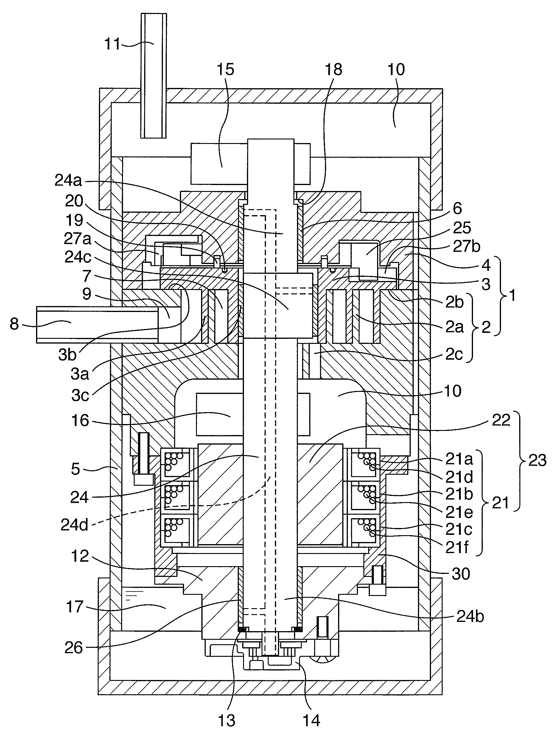
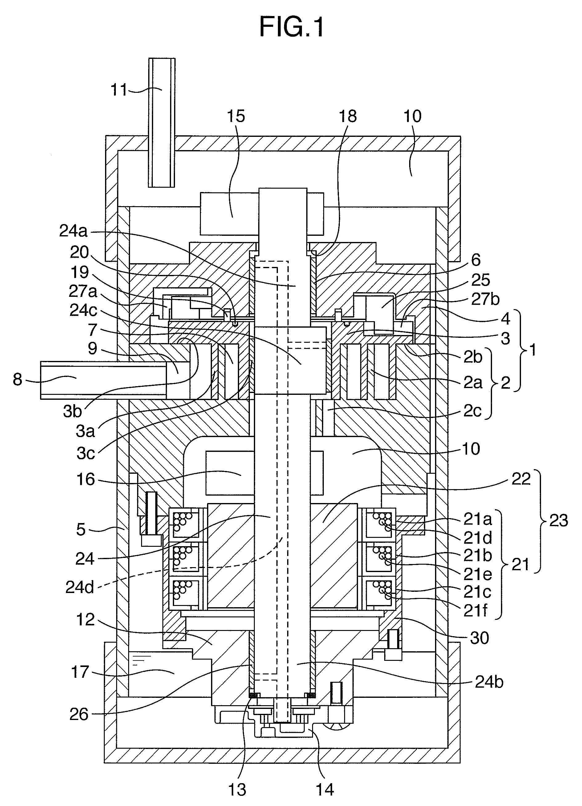
[0009]With the arrangement of the above feature, the motor is constructed using the claw-type magnetic poles formed of the magnetic powder. Therefore, it is possible to provide a displacement type compressor which is capable of being rotated at a higher speed and which has a high-energy efficiency.

Problems solved by technology

In the above-described conventional technique, the reduction in size is provided merely by eliminating a coil end portion, and hence, it is not sufficiently considered that the compressor is operated at a high output and at a high speed in a range of larger capacity.
For this reason, claw-type magnetic poles must be axially stacked as multiple layers for the purpose of an increase in output, and the increase in output results in the impairment of reduction in size for the original purpose.

Method used


Image

  • Displacement type compressor
  • Displacement type compressor
  • Displacement type compressor

Examples


third embodiment

[0050]A displacement type compressor according to the present invention will now be described with reference to FIG. 7. FIG. 7 shows the entire structure of a rotary compressor.

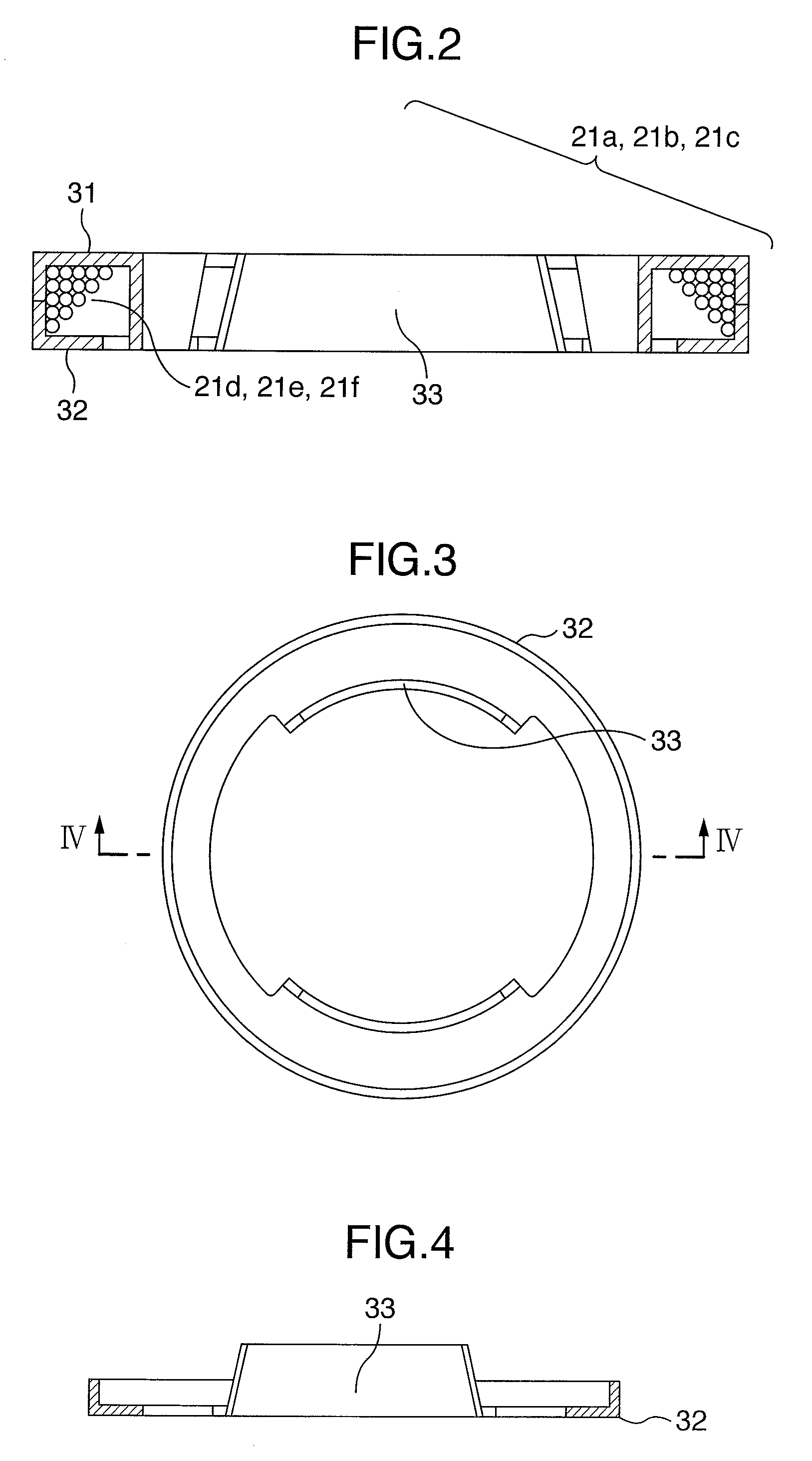
[0051]A drive source is a motor 23 which is comprised of a stator 21 comprising stator cores 21am 21b and 21c each constituted of claw-type core portions formed of a magnetic powder and meshed with each other and annular coils 21d, 21e and 21f, and a rotor 22. The stator cores 21a 21b and 21c are contained in a core frame 30.

[0052]A compressing mechanism section 101 of the rotary compressor is comprised of a cylinder 102, a first end plate 103 and a second end plate 104 for closing opposite ends of the cylinder 102, a roller 105 disposed in a space surrounded by the cylinder 102, the first end plate 103 and the second end plate 104, and a vane (not shown) having a function of changing the volume of a space defined by the cylinder 102, the first end plate 103, the second end plate 104 and the roller 105 in acc...

fourth embodiment

[0059]A displacement type compressor according to the present invention will now be described in detail with reference to FIG. 8. FIG. 8 shows the entire structure of a rotary compressor.

[0060]For a shaft support portion for a crankshaft 120, a shaft support portion 140 is provided on a second end plate 104. A thrust bearing 141 and a thrust bearing 131 for supporting an axial force of the crankshaft 120 are formed on the side of the eccentric pin portion 120c of the crankshaft 120 closer to the motor and at the first end plate 103, respectively, but both of the thrust bearings may be formed at opposite ends of the eccentric pin portion 120c of the crankshaft, and in the latter case, it is possible to provide a further simplification.

fifth embodiment

[0061]A displacement type compressor according to the present invention will now be described in detail with reference to FIG. 9. FIG. 9 shows the entire structure of a rotary compressor.

[0062]This displacement type compressor has a feature in that a compressing mechanism section 154 is disposed in a lower portion of a closed container 112 and balance weights 150 and 151 are disposed at opposite ends of a rotor 22. The balance weights 150 and 151 need not be engaged directly with the rotor 22, and may be disposed on a crankshaft. A thrust bearing 153 and a thrust bearing 152 for supporting an axial force of the crankshaft 120 are formed at opposite ends of an eccentric pin portion 120c of the crankshaft 120 for the purpose of the simplification. In place of the provision of the thrust bearing 153, a thrust load can be received on a first end plate itself, and in this case, it is possible to provide a further simplified structure.

[0063]As described above, a resinous film can be appli...


PUM


Abstract

A displacement type compressor includes a compressing mechanism section for performing a compression, a motor for driving the compressing mechanism section, and a crankshaft adapted to be driven in rotation by the motor to rotate the compressing mechanism section. The motor includes stator cores and having claw-type magnetic poles formed of a magnetic powder and circumferentially arranged in alternately meshed states, and annular coils and wound in a toric shape around the claw-type magnetic poles. Thus, the displacement type compressor is capable of being at a high speed and has a reduced size.

Description

BACKGROUND OF THE INVENTION[0001]1. Field of the Invention[0002]The present invention relates to a displacement type compressor for treating air, carbon dioxide and another compressible gas, which may be used as an HFC refrigerant or a natural refrigerant, and particularly, to a displacement type compressor which is suitably designed to provide a high output, while being small-sized.[0003]2. Description of the Related Art[0004]A displacement type compressor representative of a scroll compressor, a reciprocal compressor and a rotary compressor is widely utilized in a variety of fields not only as a compressor for a refrigerant air conditioner used for domestic, business, in-vehicle applications or the like, but also as an air supply compressor used for a source of air in a factory, for a fuel cell or the like. A high-energy efficiency is required from the viewpoint of prevention of global warming, and it is desired to reduce the size of the compressor for promoting the reduction in c...

Claims


Application Information

Patent Timeline
IPC IPC(8): F01C1/02F01C1/063
CPCF04C18/0215F04C18/3564F04C23/008F04C29/0085F04C2240/40
Inventor TSUCHIYA, TAKESHIYANAGASE, YUICHIFUJIMURA, KAZUYUKIAOKI, MAKOTOMIYAKE, MASASHIMATSUNAGA, MUTSUNORIENOMOTO, YUJIKIKUCHI, SATOSHIWAKUI, SHINICHINOZAKI, TSUTOMU
Owner HITACHI APPLIANCES INC
Learn More