Hydrogen generator and fuel cell system using the same

a fuel cell and hydrogen generator technology, applied in the direction of electrical generators, emergency supply, sustainable buildings, etc., can solve the problem of large and achieve the effect of reducing the size of the entire apparatus

Inactive Publication Date: 2007-10-04
MIURA COMPANY LIMITED
View PDF6 Cites 3 Cited by
  • Summary
  • Abstract
  • Description
  • Claims
  • Application Information

AI Technical Summary

Benefits of technology

[0023]According to the hydrogen generator and the fuel cell system using the same, a size of an entire apparatus and a running cost can be reduced. Further, the hydrogen generator and the fuel cell system can preferably be used in a facility such as a hospital or a hotel utilizing both steam and electricity.

Problems solved by technology

However, the above-mentioned facility has a reformer arranged outside, and thus an entire apparatus has a large size.

Method used


Image

  • Hydrogen generator and fuel cell system using the same
  • Hydrogen generator and fuel cell system using the same
  • Hydrogen generator and fuel cell system using the same

Examples


embodiment 1

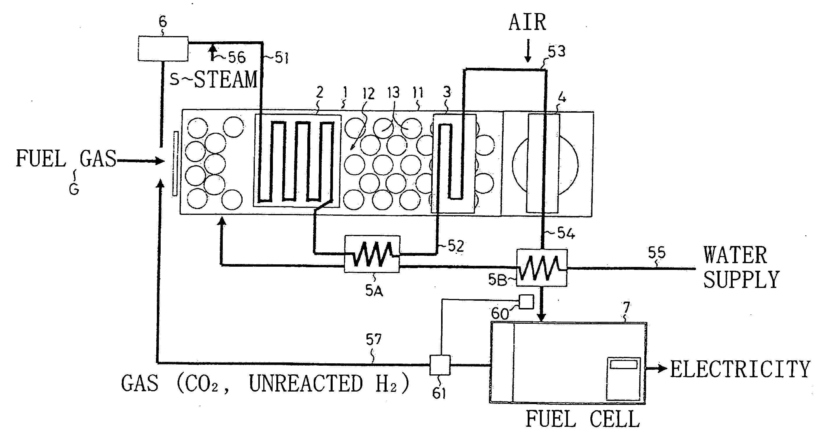
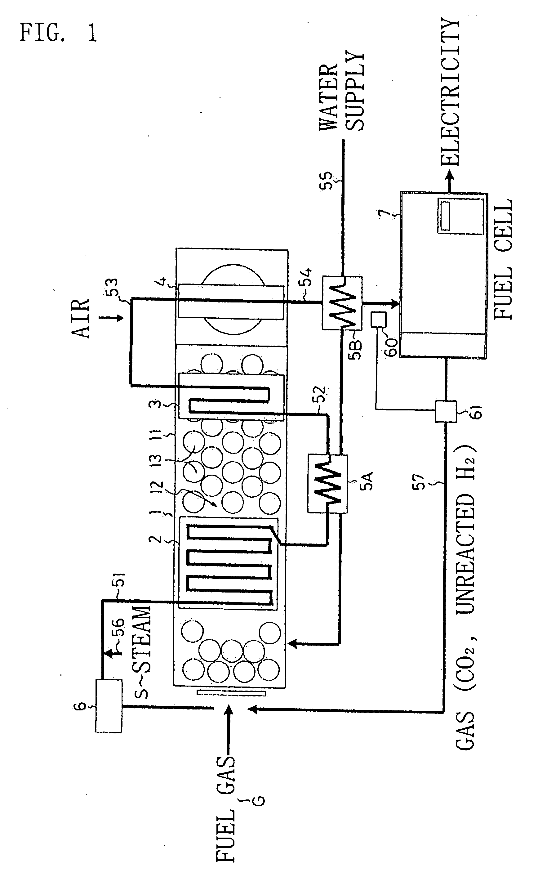
[0043]Hereinafter, a specific embodiment of a hydrogen generator according to the present invention will be described based on figures. FIG. 1 is a piping block diagram showing a fuel cell system provided with a hydrogen generator according to the embodiment of the present invention. In the embodiment shown in FIG. 1, a rectangular heat exchanger 1 having a plurality of water pipes 13 arranged in a flue gas passage 12 inside a rectangular body 11 is used, and a reformer 2 is arranged upstream of the flue gas passage 12. A converter 3 is arranged midstream of the flue gas passage 12, and a CO remover 4 is arranged downstream of the flue gas passage 12.

[0044]To an inlet side of the reformer 2, a first pipe 51 extending from a supply source of a fuel gas G such as a city gas is connected, and a desulfurizer 6 is provided in the first pipe 51. A second pipe 52 is connected between an outlet side of the reformer 2 and an inlet side of the converter 3. A third pipe 53 is connected between...

embodiment 2

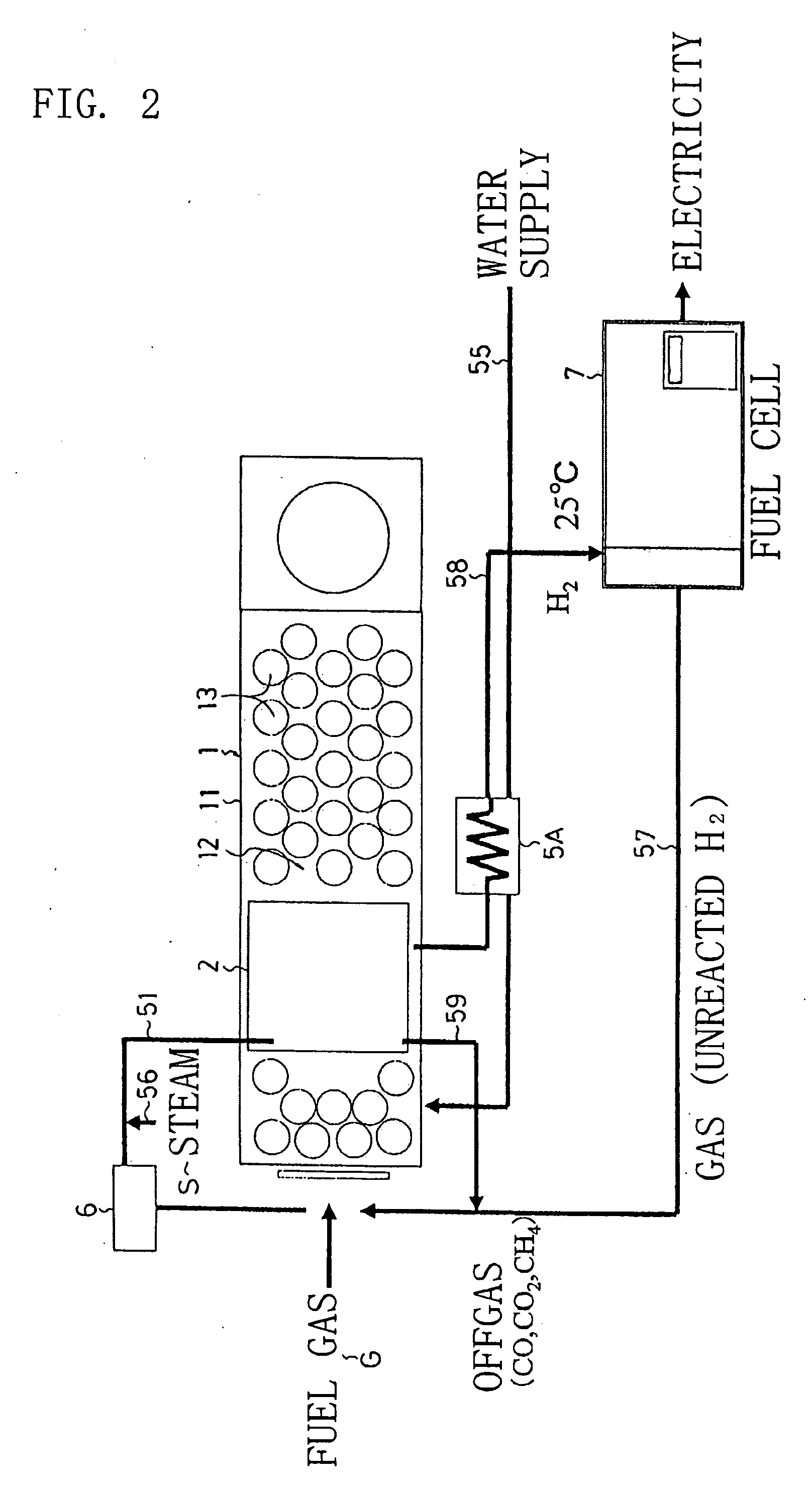
[0048]FIG. 2 is a piping block diagram showing another embodiment of the present invention. In the embodiment shown in FIG. 2: a membrane reactor-type reformer 2 is incorporated in the upstream of the heat exchanger 1; the first pipe 51 is connected to the inlet side of the reformer 2; and the outlet side of the reformer 2 is connected to the fuel cell 7 through an eighth pipe 58.

[0049]FIG. 3 is a sectional diagram showing a catalyst device used for the membrane reactor-type reformer 2. A catalyst device 8A is formed by: inserting a tubular hydrogen separation membrane 84 subjected to palladium plating or the like on a surface of a porous metal pipe into a cylinder 83 having an inlet 81 in an upper part and an outlet 82 of an off gas in a side of a lower part; projecting downwardly a lower outlet 85 of the hydrogen separation membrane 84 from the; and filling a reforming catalyst 86 such as NiO(Al2O3) inside the cylinder 83 such that the reforming catalyst 86 surrounds the hydrogen ...


PUM

PropertyMeasurementUnit
temperatureaaaaaaaaaa

Abstract

Provided is a hydrogen generator which is capable of reducing a size of an entire apparatus and reducing a running cost by utilizing heat of a heat exchanger (1) for hydrogen reforming in a reformer (2), and which can particularly preferably be used in a facility such as a hospital, a restaurant, or a hotel utilizing both steam and electricity, and a fuel cell system using the hydrogen generator. The hydrogen generator includes the reformer (2) for generating hydrogen H2 from a fuel gas G and steam H2O incorporated in a fuel gas passage (12) of the heat exchanger (1) provided with a water pipe (13). The hydrogen generator utilizes a part of heat of the heat exchanger (1) for hydrogen reforming performed in the reformer (2). The hydrogen generator includes the reformer (2), a converter (3) for generating hydrogen from carbon monoxide generated in the reformer and steam, and a CO remover (4) for removing a carbon monoxide gas generated in the converter (3). The reformer (2), the converter (3), and the CO remover (4) are arranged in the flue gas passage (12) of the heat exchanger (1).

Description

BACKGROUND OF THE INVENTION[0001]1. Field of the Invention[0002]The present invention relates to a hydrogen generator which is favorably used as a hydrogen supply source to a fuel cell to be provided in a hospital, a hotel, or the like utilizing a large volume of steam, and to a fuel cell system using the hydrogen generator.[0003]2. Description of the Related Art[0004]Conventionally, there is known a facility having a boiler (heat exchanger) and a fuel cell and provided with a reformer for generating hydrogen from a gas and steam, to thereby supply hydrogen obtained in the reformer to the fuel cell and provide hydrogen for power generation. A part of steam from the boiler is supplied to the reformer and used for hydrogen generation (see JP 06-13093 A).SUMMARY OF THE INVENTION[0005]However, the above-mentioned facility has a reformer arranged outside, and thus an entire apparatus has a large size.[0006]The present invention has been made in view of the above, and therefore an object ...

Claims


Application Information

Patent Timeline
Patent Type & Authority Applications(United States)
IPC IPC(8): H01M8/06B01J19/00
CPCB01J8/0285Y02E60/50B01J19/2475B01J2208/00141B01J2208/00203B01J2208/0053C01B3/48C01B3/501C01B2203/0233C01B2203/0283C01B2203/041C01B2203/047C01B2203/066C01B2203/0883C01B2203/0894C01B2203/1058H01M8/04014H01M8/04089H01M8/04097H01M8/0618H01M8/0668H01M8/0675H01M2250/10Y02B90/14B01J8/0496Y02B90/10
Inventor FURUKAWA, HIDEOTANAKA, OSAMUYASUI, KENJI
Owner MIURA COMPANY LIMITED
Why Eureka
Try Eureka