
Thermal energy storage system using compressed air energy and/or chilled water from desalination processes

a technology of desalination process and energy storage system, which is applied in the direction of separation process, lighting and heating apparatus, domestic cooling apparatus, etc., can solve the problems of increasing energy rates during those hours, affecting the efficiency of the home or business, and a significant portion of the energy cost to be dedicated

Inactive Publication Date: 2007-10-11
ENIS BEN M +1
View PDF29 Cites 86 Cited by
  • Summary
  • Abstract
  • Description
  • Claims
  • Application Information

AI Technical Summary

Benefits of technology

[0009] The present invention relates to an improved cooling method and system capable of reducing the end-user cost of energy, comprising an air conditioning system adapted to operate in conjunction with a thermal energy storage system, and / or a compressed air energy storage system.
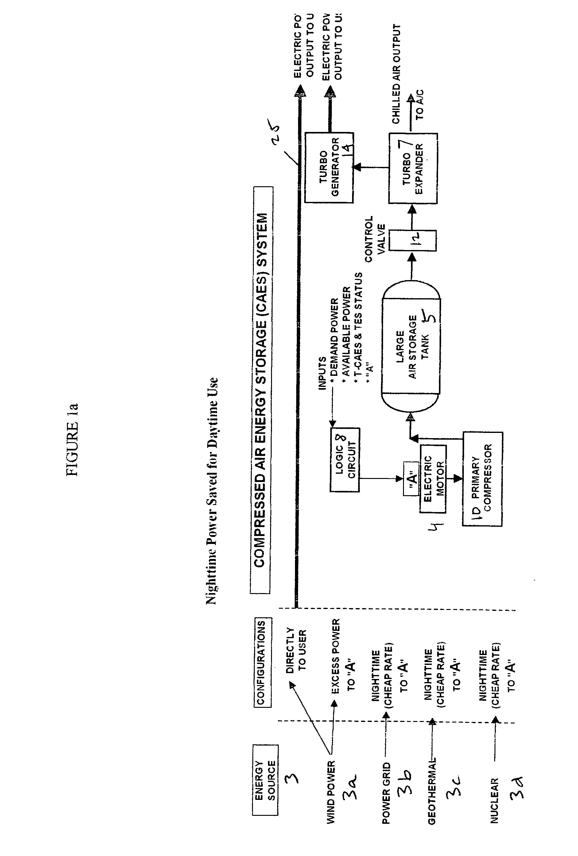
[0011] The preferred system preferably has a turbo expander to release the compressed air energy at the appropriate time, such that when the compressed air is released, the energy generated can be used in the form of either 1) electricity produced by a generator operated in connection with the compressed air energy system, or 2) chilled air generated as a by-product when the compressed air is released. These two forms of energy are preferably produced on a co-generative basis, so that one, or the other, or both, can be efficiently utilized at any given time. In this respect, consider that the compressed air energy storage system generates electricity at a relatively low efficiency rate, i.e., of close to about 30%. On the other hand, by co-generating both electricity and chilled air at the same time, and using the chilled air for secondary purposes, as will be discussed, the efficiency rate of the system can be boosted to a much higher rate, i.e., up to more than about 60%, which is desirable.

Problems solved by technology

In areas where the climate is warm, the demand for air conditioning can cause a significant portion of the energy costs to be devoted to air conditioning needs, i.e., air conditioning can become a significant factor and / or percentage of the entire energy costs, and therefore, the cost of keeping a home or business cool can become a heavy burden.
Another problem associated with keeping buildings cool is that the energy demand often peaks during the daytime hours, which, in turn, increases the energy rates during those hours.
Nevertheless, to the extent the cost of energy is higher during the highest demand periods, the cost of maintaining comfortable temperatures in the home or business can be tremendously high.
Nevertheless, energy derived from the sun, by its very nature, cannot normally be efficiently used for cooling purposes.
Although solar energy can be converted into electricity, and then, the electricity can be used to power an air conditioning system, the cost of converting the solar energy to produce electricity to do so can be prohibitively high.
The difficulty of using wind, however, is that the wind may not always blow when the demand exists.
For example, the wind can be unpredictable, and uncertain, wherein the wind may not blow with sufficient force and regularity during the times when energy is needed most.
Despite some advantages of these past systems, which attempt to store wind-generated energy, they also have certain shortcomings, making them difficult or inefficient to use.
One of the drawbacks of these systems, however, is that the energy must be purchased directly from the utility companies, notwithstanding that it can be purchased at a lower rate during off-peak hours.

Method used


Image

  • Thermal energy storage system using compressed air energy and/or chilled water from desalination processes
  • Thermal energy storage system using compressed air energy and/or chilled water from desalination processes
  • Thermal energy storage system using compressed air energy and/or chilled water from desalination processes

Examples


Embodiment Construction

[0050] 1. System Components:

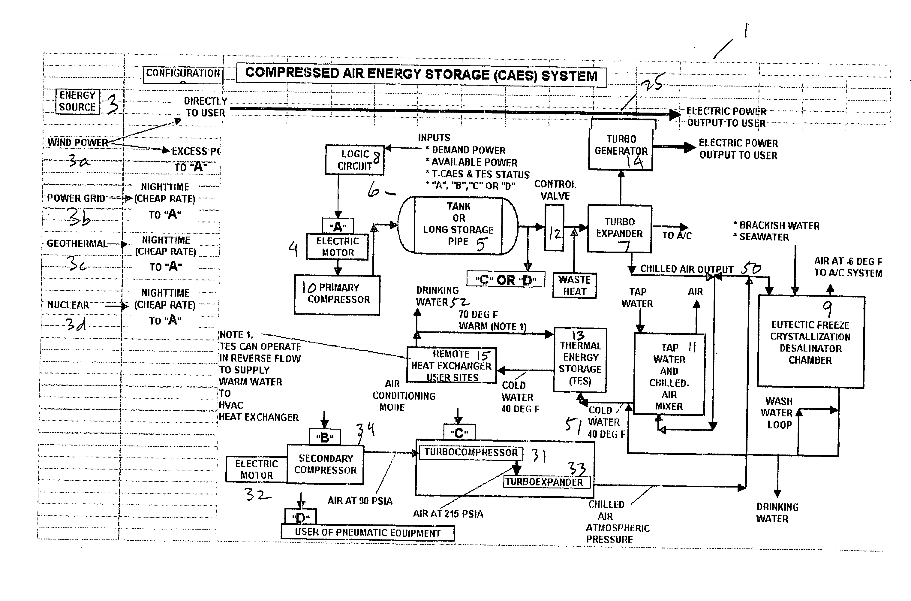
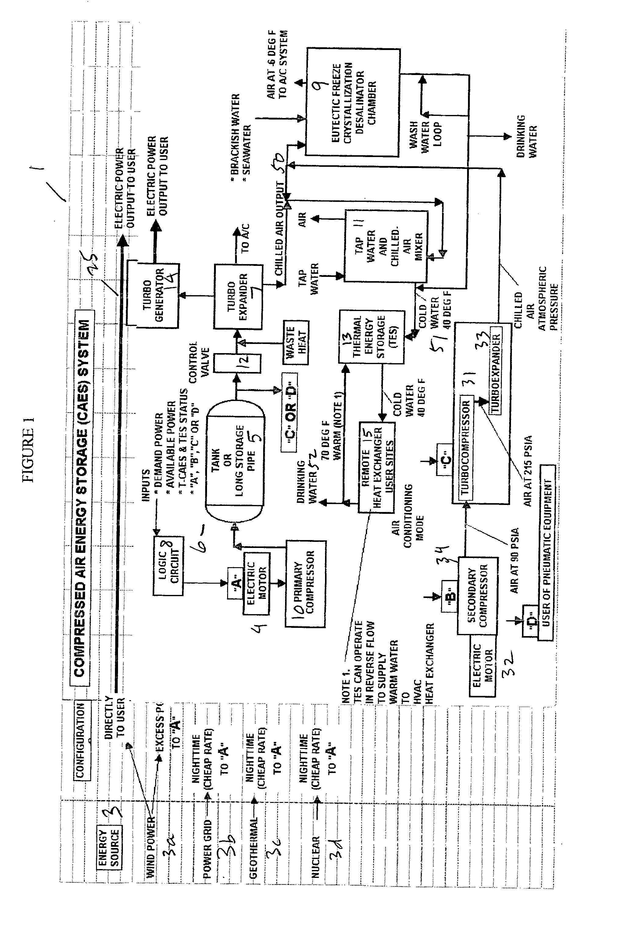
[0051]FIG. 1 is a schematic diagram showing a universal embodiment that contains all components and features for all scenarios in a single system 1. Generally speaking, it contains an energy source 3, a primary compressor 10, a compressed air energy storage tank 5, a turbo expander 7 for releasing the compressed air, a turbo generator 14 for generating electricity using the compressed air, a desalination system 9 for using the chilled air generated by the turbo expander to produce chilled fresh water, a mixing chamber 11 for using the chilled air to produce chilled water, a thermal energy storage unit 13 with separation tank for storing the chilled water, and an air conditioning system 15 that uses the chilled water to produce chilled air for cooling. There can also be a secondary compressor 34, additional heat exchangers, etc.

[0052] The major system components consist of the following:

[0053] Energy Source

[0054] Compressed Air Energy Storage System

[0...


PUM

PropertyMeasurementUnit
equilibrium temperatureaaaaaaaaaa
energyaaaaaaaaaa
wind energyaaaaaaaaaa

Abstract

The invention relates to a universal system for producing cost effective energy particularly for cooling purposes. In one embodiment, wind turbines are used to generate electricity and compressed air energy, wherein the compressed air energy is used to co-generate electricity and chilled air. The chilled air is then used to chill water in either a mixing chamber, or a desalination system, wherein the chilled water is stored in a separation tank, wherein it can later be used to provide cooling for an air conditioning system for a facility. When desalination is used, the system produces chilled fresh drinking water which can be used for air conditioning, and then used as fresh drinking water. Any exhaust chilled air can be used directly for air conditioning.

Description

RELATED APPLICATIONS [0001] This application claims the benefit of the filing dates of U.S. provisional application No. 60 / 789,415, filed Apr. 5, 2006, 60 / 794,190, filed Apr. 21, 2006, and 60 / 832,777, filed Jul. 24, 2006, which are all incorporated herein by reference.BACKGROUND OF THE INVENTION [0002] In many areas of the country, air conditioning needs are significant, especially during summer months. In some states, such as Florida and Texas, and others in the south, those needs are significant throughout most of the year. Not only do high outdoor temperatures affect indoor temperatures whenever large windows are used, but there is typically a substantially increased need for cooling to offset the greenhouse effect that can cause heat to be trapped inside. In areas where the climate is warm, the demand for air conditioning can cause a significant portion of the energy costs to be devoted to air conditioning needs, i.e., air conditioning can become a significant factor and / or perc...

Claims


Application Information

Patent Timeline
Patent Type & Authority Applications(United States)
IPC IPC(8): F25B9/00F25B27/00F25D17/02
CPCC02F1/22C02F2103/08C02F2201/001C02F2201/009Y02E60/15F02C6/16F25B27/00Y02E20/14C02F2209/02Y02W10/37Y02A20/211Y02A20/141Y02A20/212Y02A20/124Y02E60/16
Inventor ENIS, BEN M.LIEBERMAN, PAUL
Owner ENIS BEN M
Learn More