
Asymmetric capillary for capillary-flow cytometers

a flow cytometer and asymmetric capillary technology, applied in the field of flow cytometers, can solve the problems of time-dependent pulse shape variation, inability to accurately measure samples, and inability to meet the requirements of the bench-top system with more limited capabilities, so as to improve the measurement cv and reduce the position-dependent variation of pulse shape and amplitude. , the effect of improving the measuremen

Inactive Publication Date: 2007-10-11
MILLIPORE CORP
View PDF4 Cites 11 Cited by
  • Summary
  • Abstract
  • Description
  • Claims
  • Application Information

AI Technical Summary

Benefits of technology

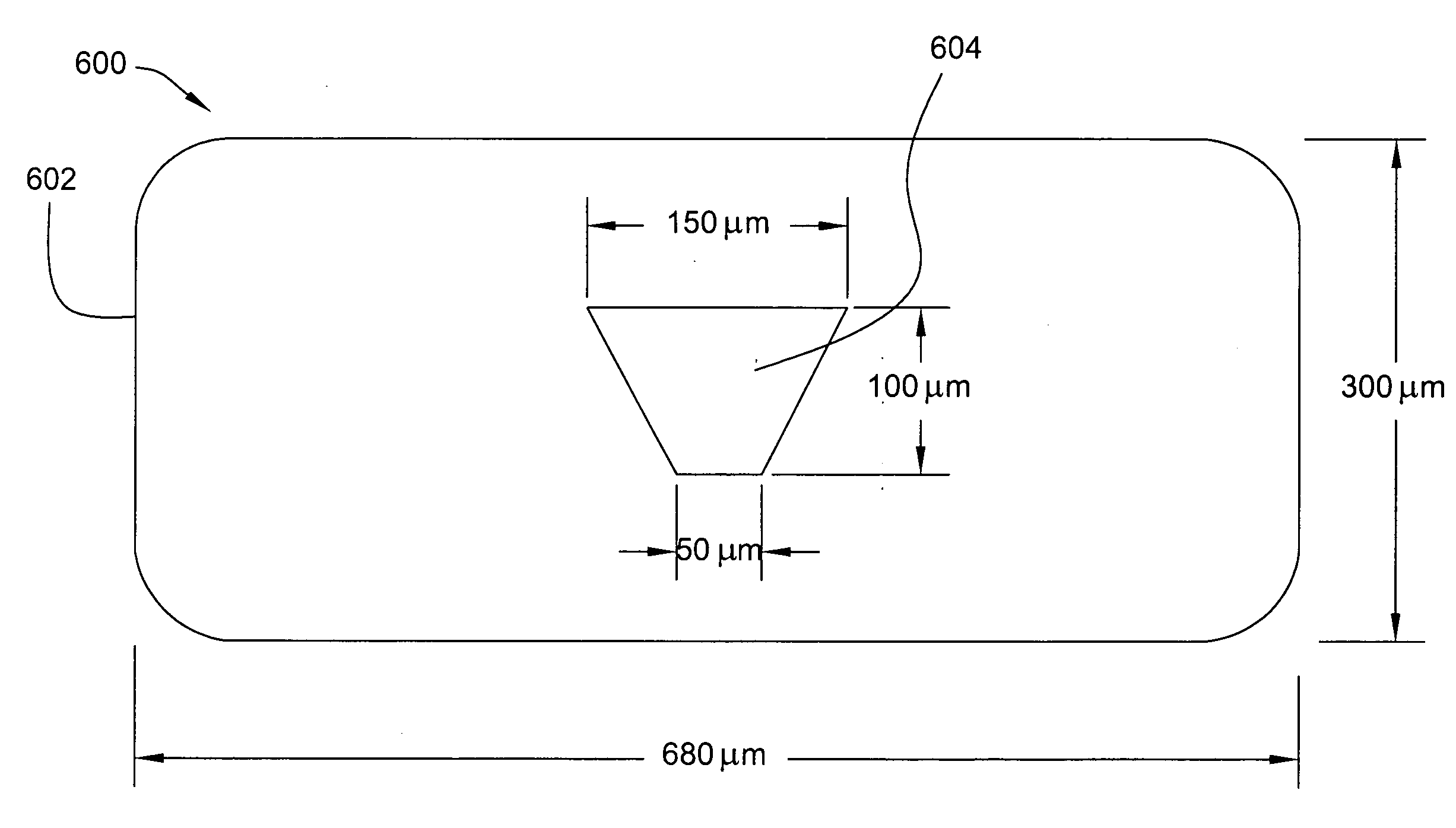
[0041]In view of the foregoing, the present invention provides improved capillaries for use in capillary-flow cytometers. The cross-sectional shape of capillaries made according to the present invention lack point symmetry. This significantly reduces position dependent variations in pulse shape and amplitude caused by scattering and refraction of light by the capillary walls. The shape of the outer and inner capillary walls lowers (improves) the measured CV.
[0042]In some embodiments, capillaries have inner side walls that are tilted at angles with respect to the collection-system optical axis so that the widest dimension of the inner bore is closest to the collection optical system and have an outer wall closest to the collection optical system with a dimension large enough to minimize the contribution of outer-wall refraction to the collected light signal. The position-sensitive variation in collected light and the associated contribution to measured CV can be minimized by selecting the inner-wall tilt angle and outer-wall dimension according to the numerical aperture and field-stop diameter of the collection optical system.
[0044]Further embodiments of the invention minimize the amount of scattered excitation light entering the collection optical system by having wall dimensions in the direction parallel to the collection axis that are large enough to minimize interactions between the excitation beam and the outer wall.

Problems solved by technology

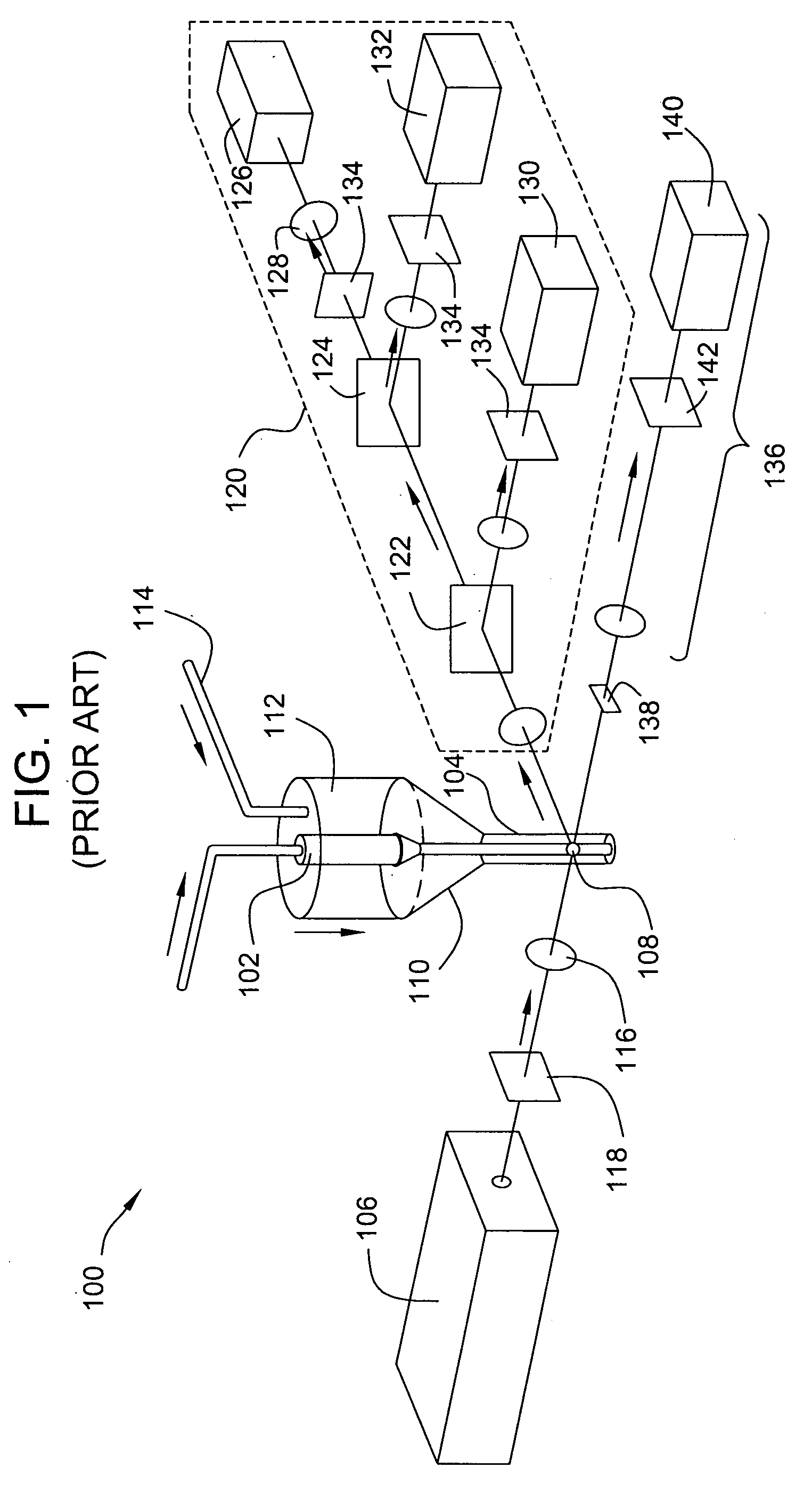
Commercially available instruments range from complex laboratory systems that may be configured for a wide range of measurements to low-cost bench-top systems with more limited capabilities.
Errors in the sample-particle detection process are caused by the simultaneous illumination of multiple sample particles and by variations in the amplitude and shape of pulses that are generated by identical sample particles.
Deviations from the laminar-flow condition (turbulent flow) lead to unpredictable, time-dependent pulse-shape variations.
Sheath-flow cells are complex, expensive, and difficult to align properly.
Variations in the pulse amplitudes produced by identical particles lead to counting errors and thus to an undesirable increase of the CV for a measurement.
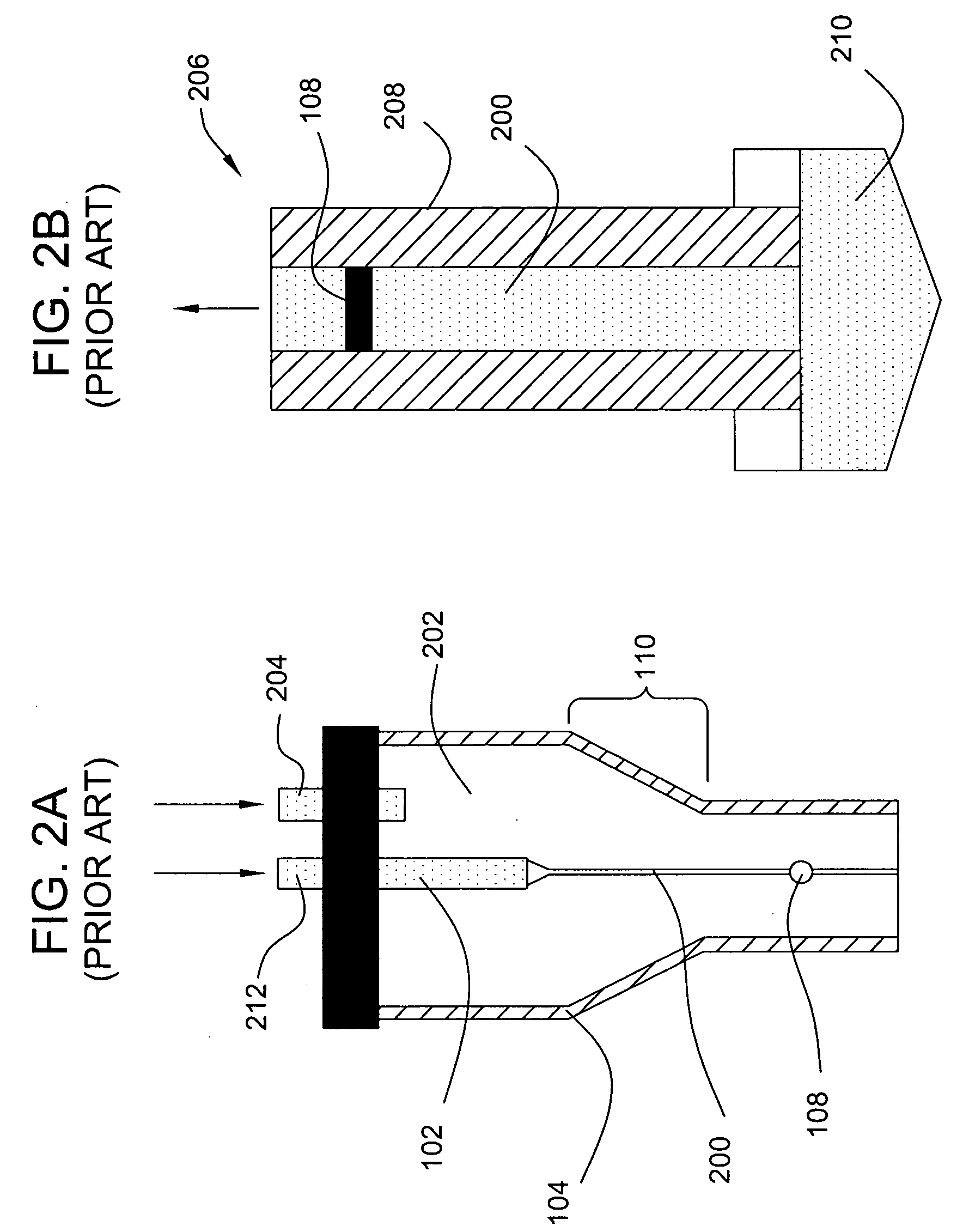
Capillary clogging is fatal to any measurement and places a practical lower limit on the bore dimension of a square capillary 208 that is determined by the size of the particles.
Economical and efficient methods for reducing wall effects are unknown in the prior art.

Method used


Image

  • Asymmetric capillary for capillary-flow cytometers
  • Asymmetric capillary for capillary-flow cytometers
  • Asymmetric capillary for capillary-flow cytometers

Examples


Embodiment Construction

[0056]Turning to the drawings, wherein like reference numerals refer to like elements, the present invention is illustrated as being implemented in a suitable environment. The following description is based on embodiments of the invention and should not be taken as limiting the invention with regard to alternative embodiments that are not explicitly described herein.

[0057]Position-dependent variations in pulse shape and in amplitude caused by scattering and refraction of light by the capillary walls in prior art capillary-flow cytometers may be significantly reduced through the use of improved capillary designs. In contrast to the square and round capillaries of the prior art, the cross-sectional shapes of the improved capillaries lack point symmetry. The replacement of a conventional square capillary with an asymmetric capillary embodying the present invention minimizes wall effects. CVs for fluorescent counting measurements performed by capillary-flow cytometers incorporating the ...


PUM


Abstract

The present invention provides improved capillaries that lead to increased resolution in conventional capillary-flow cytometers. The cross-sectional shape of capillaries made according to the present invention lack a center of symmetry. In some embodiments, capillaries have inner side walls that are tilted at angles with respect to the collection-system optical axis so that the widest dimension of the inner bore is closest to the collection optical system and have an outer wall closest to the collection optical system with a dimension large enough to minimize the contribution of outer-wall refraction to the collected light signal. Exemplary capillary embodiments include tubes with a rectangular outer wall and a trapezoidal inner wall, a rectangular outer wall and a triangular inner wall, triangular outer and inner walls, a triangular outer wall with a trapezoidal inner wall, and a hemispherical or rhomboid outer wall and trapezoidal or triangular inner wall.

Description

CROSS-REFERENCE TO RELATED APPLICATION[0001]This application claims priority to U.S. Provisional Patent Application 60 / 791,002, “Improved Capillary Design for Capillary Flow Cytometers,” which was filed on Apr. 11, 2006, and which is incorporated herein by reference in its entirety.FIELD OF THE INVENTION[0002]The present invention relates generally to flow cytometers for counting particles, and, more particularly, to capillary-flow cytometers.BACKGROUND OF THE INVENTION[0003]Flow-cytometer systems are used for the detection and counting of micro-organisms and for varied applications throughout the life sciences including clinical diagnostics and immunology, protein and nucleic acid detection, hematology, and oncology. Commercially available instruments range from complex laboratory systems that may be configured for a wide range of measurements to low-cost bench-top systems with more limited capabilities. In the current biotechnology market, the price of a flow cytometer typically i...

Claims


Application Information

Patent Timeline
IPC IPC(8): G01N21/00
CPCG01N15/1404G01N2015/1415G01N2015/0053
Inventor ILKOV, FEDOR A.
Owner MILLIPORE CORP
Learn More