Complex filter with automatic tuning capabilities

a complex filter and automatic tuning technology, applied in the field of receivers, can solve the problems of complex filter sensitive to some circuit parameters, affecting the if signal, and affecting the performance of the receiver,

Inactive Publication Date: 2007-10-11
O2 MICRO INC
View PDF0 Cites 25 Cited by
  • Summary
  • Abstract
  • Description
  • Claims
  • Application Information

AI Technical Summary

Benefits of technology

[0010] In one embodiment, there is disclosed a complex filter with automatic tuning capabilities for filtering a complex signal. The complex signal has an imaginary component and a real component. The complex filter includes a first lowpass filter, a second lowpass filters, a plurality of resistors, an integrator, a comparator, and a digital unit. The first lowpass filter receives the imaginary component of the complex signal and generates a signal as an output signal of the complex filter. The second lowpass filter receives the real component of the complex signal. The plurality of resistors are coupled between the first and the second lowpass filters. The integrator receives a first reference voltage and generates an output signal. The comparator compares the output signal from the integrator with a second reference voltage and generates a digital signal according to a result of comparison. The digital unit receives the digital signal and generates a first control signal, a second control signal, a third control signal and a fourth control signal. The fourth control signal is delivered to the first and the second lowpass filters.
[0011] In yet another embodiment, there is disclosed a tuning system for a complex filter. The tuning system includes a tuning circuit, a transistor, and a final latch. The tuning circuit generates a latch up signal. The tuning circuit includes an integrator, a comparator, and a digital unit. The integrator receives a first reference voltage and generates an output signal. The comparator compares the output signal from the integrator with a second reference voltage and generates a digital signal. The digital unit receives the digital signal and generates a first control signal, a second control signal, a third control signal and a fourth control signal. The fourth control signal is used to tune the complex filter to a predetermined frequency. The transistor receives the latch up

Problems solved by technology

During the signal processing or transmission, noises and/or other undesirable signals may occur and affect the IF signals.
However, the disadvantage of the cascade-pole metho

Method used


Image

  • Complex filter with automatic tuning capabilities
  • Complex filter with automatic tuning capabilities
  • Complex filter with automatic tuning capabilities

Examples


Embodiment Construction

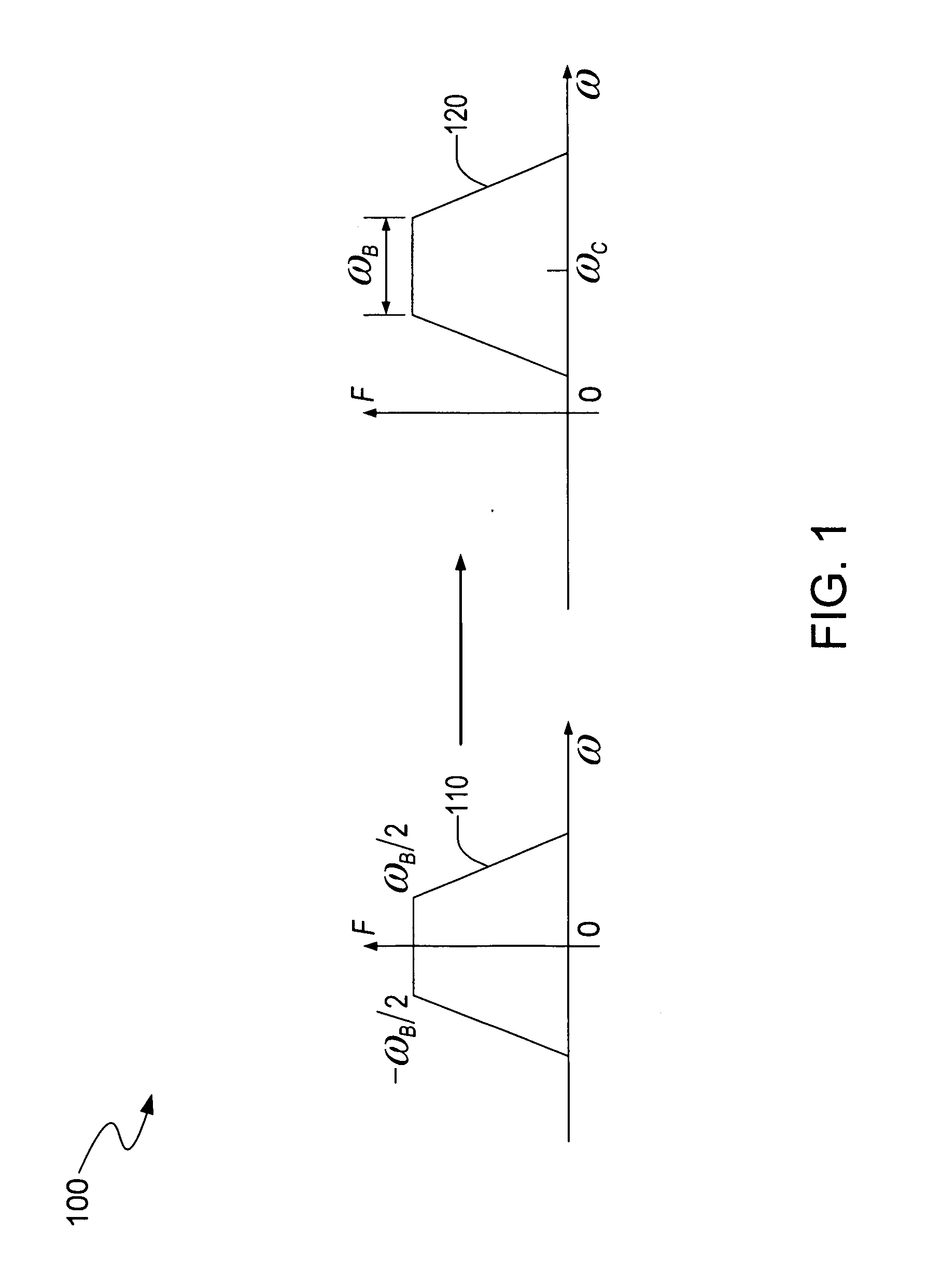
[0024] The invention provides direct synthesis of a complex filter from its leapfrog lowpass prototype. The direct synthesis of the complex filter from its leapfrog lowpass prototype makes the complex filter less sensitive to the tolerance of the component values. FIG. 1 is a schematic diagram 100 that illustrates characteristics of frequency transform of a complex filter and its lowpass prototype (a lowpass filter). Plot 110 illustrates the transfer function of the lowpass prototype whose bandwidth is ωB. The cutoff frequencies of the lowpass prototype are −ωB / 2 and ωB / 2, respectively. Plot 120 depicts the transfer function of the complex filter. The transfer function of the complex filter can be shifted to a center frequency, compared with that of its lowpass prototype. The shift of the transfer function of the complex filter can be expressed by equation (1).

HC(ω)=HL(ω−ωC)  (1)

[0025] Wherein HC(ω) is the transfer function of the complex filter, HL(ω) is the transfer function of ...


PUM


Abstract

A complex filter with automatic tuning capabilities for filtering a complex signal is disclosed. The complex filter includes a first lowpass filter, a second lowpass filter, a plurality of resistors, an integrator, a comparator, and a digital unit. The complex filter includes an imaginary component and a real component. The integrator, the comparator and the digital unit forms a tuning circuit. The tuning circuit can generate a plurality of control signals to tune the complex filter to a predetermined frequency. The tuning circuit can be turned off after a predetermined period.

Description

RELATED APPLICATION [0001] This application claims the benefit of U.S. provisional application, titled Complex Filter Based on Leapfrog Lowpass Prototype with Mixed-Signal Automatic Tuning System, Ser. No. 60 / 778,222, filed on Mar. 2, 2006, the specification of which is incorporated herein in its entirety by this reference.BACKGROUND OF THE INVENTION [0002] 1. Field of the Invention [0003] The present invention relates to receivers and in particular to low-IF (intermediate frequency) receivers. [0004] 2. Description of the Related Art [0005] Receivers are commonly used in RF (radio frequency) signal transmission. In wireless communication field, the receivers are usually used to receive RF signals. The receivers convert these RF signals to desirable IF signals and transfer these IF signals to their destination where the IF signals are used. The receivers are widely employed in telecommunication, for example, use in wireless network access points. [0006] The receivers (e.g., wide ban...

Claims


Application Information

Patent Timeline
IPC IPC(8): H04B1/10
CPCH03H11/1291H03H11/1247H03H2011/0494
Inventor TAN, SEETECKDINGKUN, DUYONGMING, LI
Owner O2 MICRO INC
Why Eureka
Try Eureka