Microbattery Comprising Through-Connections and Production Method Thereof

a micro-battery and through-connection technology, applied in the field of micro-battery, can solve the problems of difficult to achieve and limited surface availability, and achieve the effect of reducing the size of the micro-battery

Inactive Publication Date: 2007-10-11
COMMISSARIAT A LENERGIE ATOMIQUE ET AUX ENERGIES ALTERNATIVES
View PDF7 Cites 38 Cited by
  • Summary
  • Abstract
  • Description
  • Claims
  • Application Information

AI Technical Summary

Benefits of technology

[0011] One object of the invention is to remedy these shortcomings and in particular to minimize the size of a microbattery and to avoid a localized opening step of the contacts in the final phase of fabrication.

Problems solved by technology

Moreover, when the microbattery is fitted on an integrated circuit chip, the available surface is often very limited.
Only the contact pads do not have to be covered, which is difficult to achieve, especially on a finished device.

Method used


Image

  • Microbattery Comprising Through-Connections and Production Method Thereof
  • Microbattery Comprising Through-Connections and Production Method Thereof
  • Microbattery Comprising Through-Connections and Production Method Thereof

Examples


Embodiment Construction

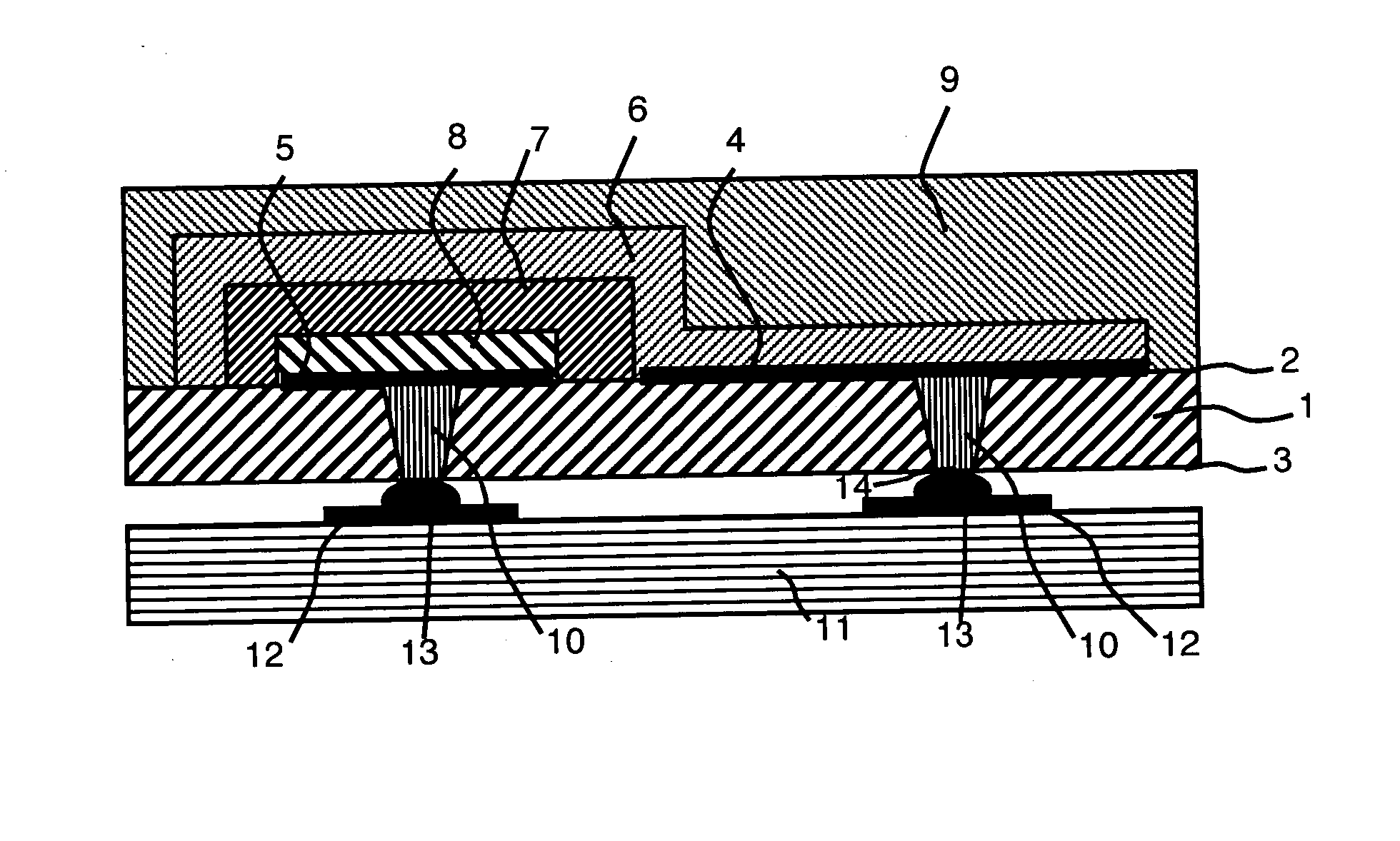
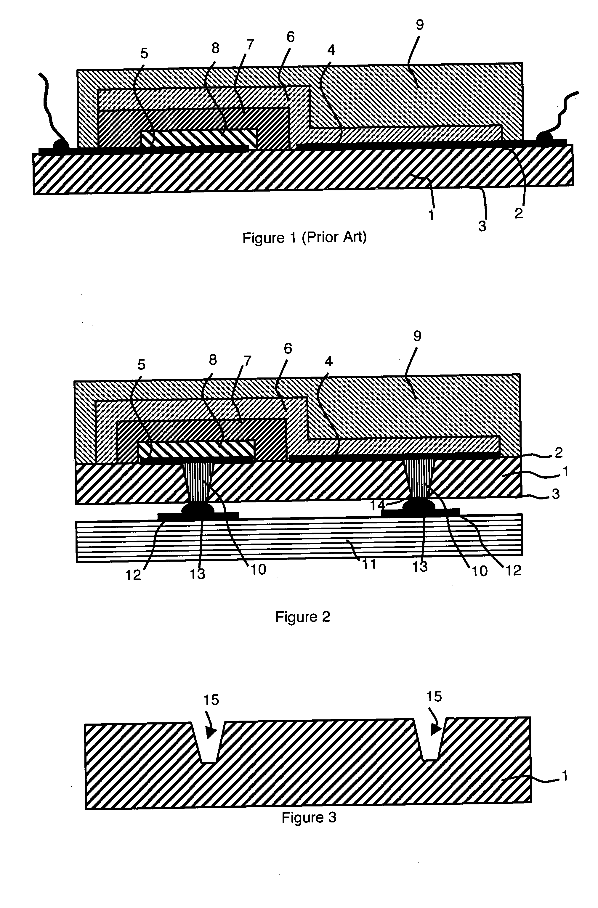
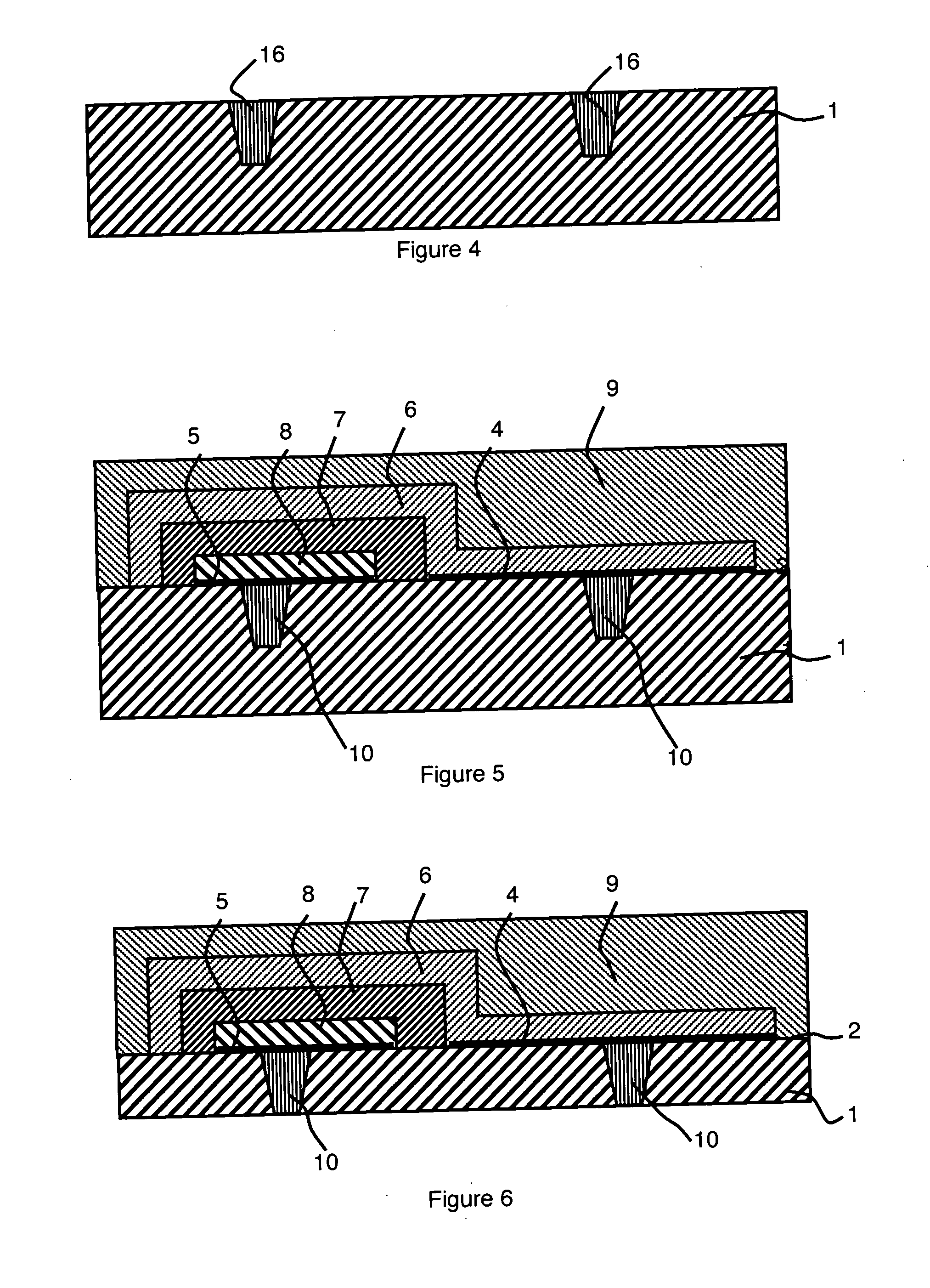
[0022] The microbattery represented in FIG. 2 comprises a support 1, preferably made from silicon, having a front face 2 and a rear face 3. The silicon support presents the advantage of being compatible with deposition methods based on microelectronics techniques. A first current collector 4 and a second current collector 5 are arranged on the front face 2 of the support 1. A stack comprising a cathode 8 and an anode 6 separated by an electrolyte 7 is arranged on the current collectors 4 and 5. The anode 6 and cathode 8 are respectively in contact with the first current collector 4 and the second current collector 5. A protective layer 9 covers said stack and thereby ensures tight sealing of the microbattery. The first 4 and second 5 current collectors are in contact with connections 10 passing through the support 1 from the front face 2 to the rear face 3 thereof.

[0023] In the particular embodiment represented in FIG. 2, the stack covers substantially the whole of the front face 2...


PUM

PropertyMeasurementUnit
total thicknessaaaaaaaaaa
thicknessaaaaaaaaaa
thicknessaaaaaaaaaa

Abstract

A microbattery has a support having a front face, a rear face, first and second current collectors arranged on the front face. A stack including a cathode and an anode separated by an electrolyte is arranged on the current collectors. The anode and cathode respectively contact the first and second current collectors. A protective layer covers the stack. The microbattery has connections in contact with the first and second current collectors, passing through the support from the front face to the rear face. The stack substantially covers of the front face of the support. A method for producing the mircobattery includes etching cavities, in the front face of the support, having a depth that is smaller than the thickness of the support, filing of the cavities with a conducting material and removing a layer of the rear face of the support to uncover the conducting material in the cavities.

Description

BACKGROUND OF THE INVENTION [0001] The invention relates to a microbattery comprising [0002] a support having a front face and a rear face, [0003] first and second current collectors arranged on the front face of the support, [0004] a stack comprising an anode and a cathode separated by an electrolyte, the anode and cathode being in contact respectively with the first and second current collectors, [0005] a protective layer covering said stack, [0006] electrical connection means in contact with the first and second current collectors. STATE OF THE ART [0007] As represented in FIG. 1, microbatteries conventionally comprise a support 1 having a front face 2 and a rear face 3 and whereon a first current collector 4 and a second current collector 5 and a stack comprising an anode 6 and a cathode 8 separated by an electrolyte 7 are arranged. The anode 6 and cathode 8 are in contact respectively with the first 4 and second 5 current collectors. The current collectors 4 and 5 usually compr...

Claims


Application Information

Patent Timeline
Patent Type & Authority Applications(United States)
IPC IPC(8): H01M2/00H01M6/00H01M50/528H01M4/04H01M10/04H01M10/052H01M10/0562H01M10/0585H01M10/36H01M50/117H01M50/121
CPCH01M2/0257H01M4/0421H01M6/40H01M10/0436Y10T29/49115H01M10/0562H01M10/0585Y02E60/122H01M10/052Y02E60/10Y02P70/50H01M50/121H01M50/117H01M6/18H01M2300/0068
Inventor LAURENT, JEAN-YVESSALOT, RAPHAELMARSACQ, DIDIERZUSSY, MARC
Owner COMMISSARIAT A LENERGIE ATOMIQUE ET AUX ENERGIES ALTERNATIVES
Why Eureka
Try Eureka