Osteosynthesis plate, method of customizing same, and method for installing same

Inactive Publication Date: 2007-10-11
LOVALD SCOTT
View PDF19 Cites 221 Cited by
  • Summary
  • Abstract
  • Description
  • Claims
  • Application Information

AI Technical Summary

Benefits of technology

[0014]For patient customization, the ideal size parameters of a previously designed osteosynthesis plate for each patient can be determined through stress or strain analysis given a data input for each patient. Given patient input data including, for example, fracture location and bone quality, either a customized plate design or category of plate design and size can be determined for the patient. The determination can be based upon geo

Problems solved by technology

The problem with this approach is that while this plate is a solid and stable structure adapted to fit the contours of many long bones, as a stabilizing structure it is over engineered as much of its solid material is not required to stabilize many common bone fractures throughout the body.
In the case of osteosynthesis bone plates, stability of the fracture line is the primary concern of the implant as many complications stem from instability of the fracture region.
While maximal stability of the fracture can be achieved through increasing the size and strength of the plate, there is both a limited number of materials capable of safe permanent implantation within the body and a limit to the size and shape of plates as increasing the volume of the plate can eventually cause complications due to the intrusive nature of the implant.
Plate palpability, thermal sensitivity and stress shielding of bone are some complications incurred with plates of larger strength and volume.
Furthermore, excessively large and stiff bone plates are cumbersome during surgery

Method used


Image

  • Osteosynthesis plate, method of customizing same, and method for installing same
  • Osteosynthesis plate, method of customizing same, and method for installing same
  • Osteosynthesis plate, method of customizing same, and method for installing same

Examples


Example

[0029]The present invention describes an implant for osteosynthesis, a method for installing same, a method for designing same, and a method for customizing same. The present invention may be specifically appropriate for designing, customizing, and installing plates for cranio maxillofacial surgery, though the invention is applicable to other types of surgery. References to fixation of fractures of the mandible, midface, and upper face are exemplary only.

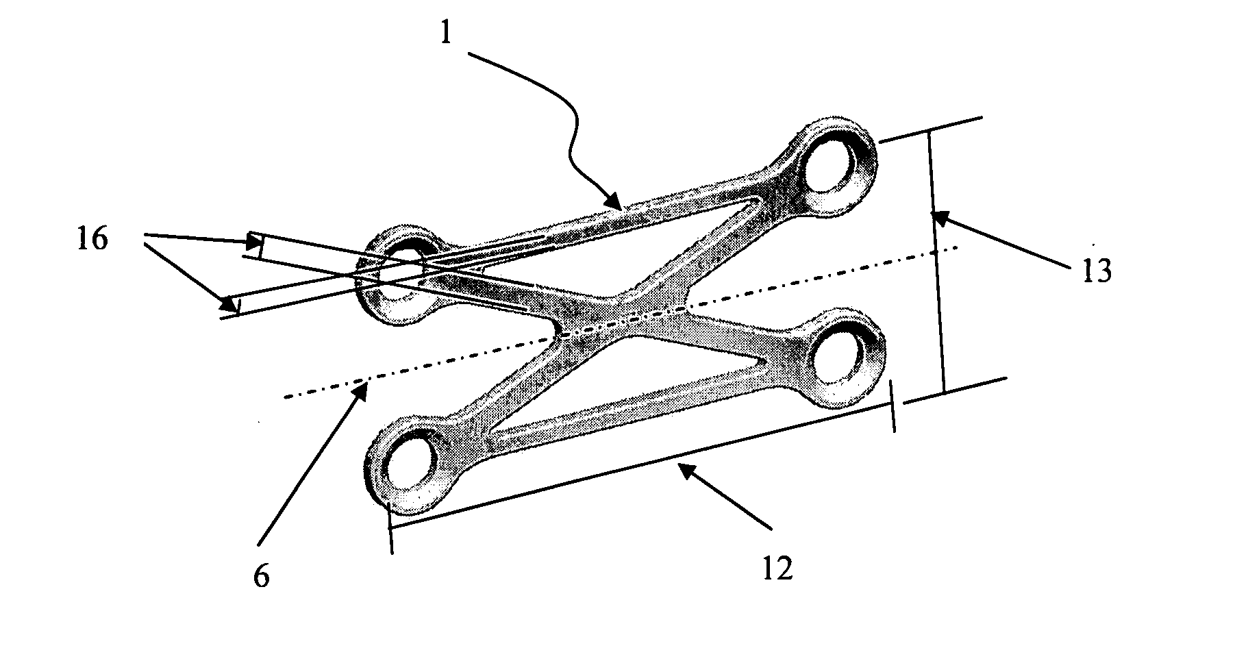
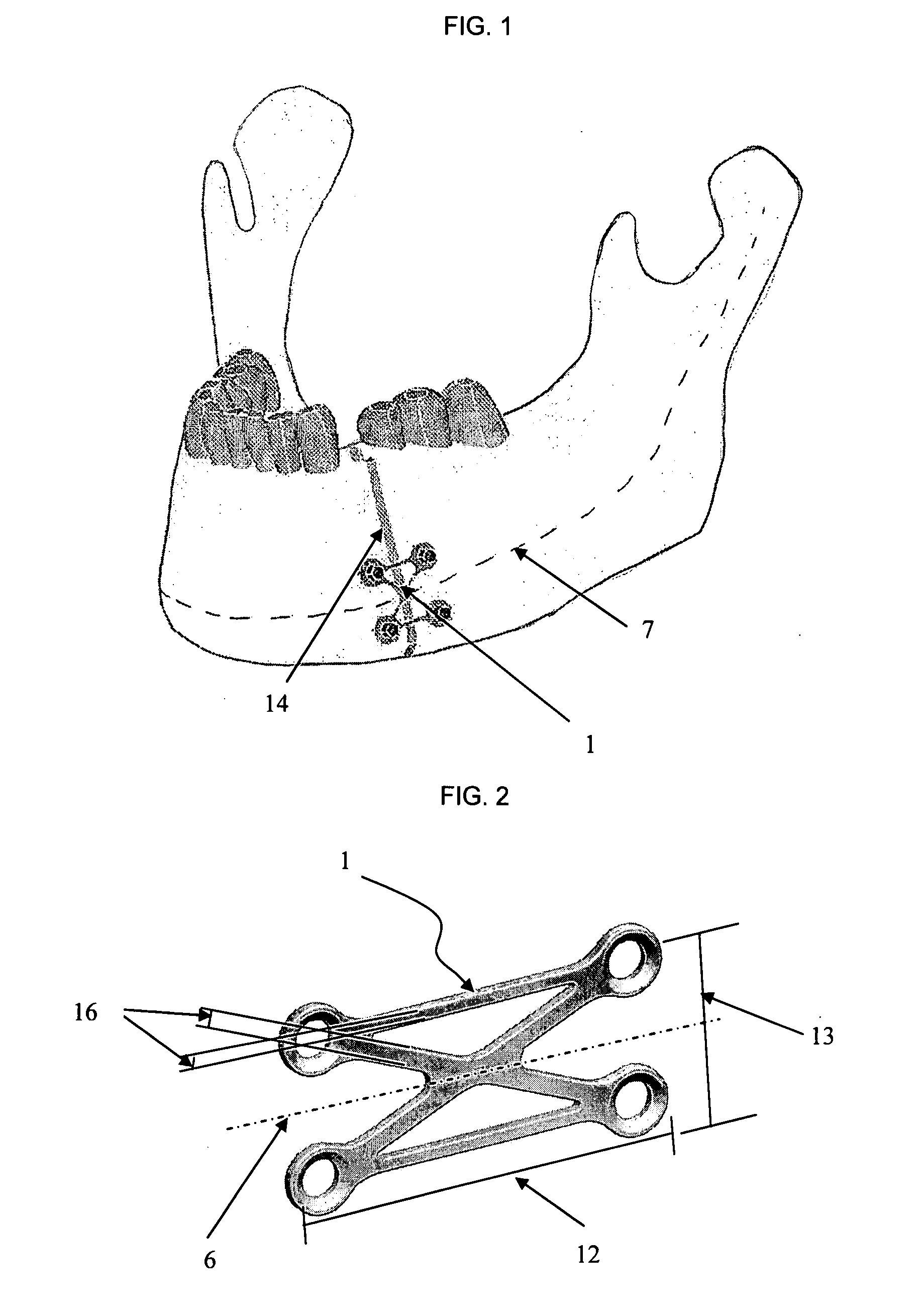
[0030]FIG. 1 shows a fracture 14 of the mandible fixated with an osteosynthesis plate 1. Mandibular fractures 14 can be located in different regions and can vary significantly in their severity. Rigid fixation of a fracture can be achieved by removing tissue to expose a bone fracture, bridging the fracture with an osteosynthesis plate, and securing the fixation plate to the patient anatomy by means of screws, pins, or tines. The purpose of rigid fixation of fractures is to provide adequate stability of the fracture so that a patient...


PUM


Abstract

An implant for osteosynthesis used in the stabilization of fractured bone of the mandible. The plate consists of apertures through which the plate is secured to bone using surgical screws. The apertures are connected by (a) two lateral bar sections running approximately parallel to the long axis of the mandible and (b) two cross bar sections intersecting each other near the centroid of the plate and at acute angles to the lateral bar sections. The plate design can be modified to accommodate patient anatomy depending on the type of bone it is designed to stabilize. Design and size parameters of the fixation plate can be customized to each individual patient using a customization software application to determine the least invasive fixation plate that will provide adequate functioning in stabilizing the bone fracture to a degree that will allow safe bone healing. The invention includes a method of design of osteosynthesis plates using shape optimization for different types and locations of fractures.

Description

CROSS REFERENCE TO RELATED APPLICATIONS [0001]Provisional Application 60 / 790,488; filed Apr. 10, 2006; Applicant: Lovald; Title: Cranio maxillofacial implant device customization software.[0002]Provisional Application 60 / 850,207; filed Oct. 10, 2006; Applicant: Lovald; Title: Osteosynthesis plate, method for customizing same, and method for installing same to stabilize bone fractures.BACKGROUND OF THE INVENTION[0003]1. Technical Field of. Invention[0004]The present invention pertains to a plate for fixation of broken bones. The osteosynthesis plate was designed to provide maximal stability over a bone fracture with a minimum of material and intrusion to the patient. The size of the shape of the fixation plate can be customized for each patient using a software application.[0005]2. Description of Prior Art[0006]U.S. Pat. No. 4,503,848 to Caspar, et al, issued Mar. 12, 1985 for an osteosynthesis plate shows a way to make possible the effective immobilization of pieces of bone with an ...

Claims


Application Information

Patent Timeline
IPC IPC(8): A61C8/00A61B17/58
CPCA61B17/8071A61B2017/00004A61B17/8085
Inventor LOVALD, SCOTTWAGNER, JON D.
Owner LOVALD SCOTT
Why Eureka
Try Eureka