
Shock wave generators

a generator and shock wave technology, applied in the field of shock wave generators, can solve the problems of only having a reduced usage period for therapy heads, affecting the effect of shock wave generation,

Inactive Publication Date: 2007-10-11
TISSUE REGENERATION TECH
View PDF6 Cites 15 Cited by
  • Summary
  • Abstract
  • Description
  • Claims
  • Application Information

AI Technical Summary

Benefits of technology

[0036] It is therefore the object of the invention to provide an alternative which is cost-saving as well as user-friendly.
[0044] A distance of the electrodes which is high as possible is desirable, since it leads to an increased lifetime of the electrodes, promotes a high steepness of the pressure increase of the shock wave, and leads to small leakage currents, thus increasing the efficiency factor.
[0048] It is therefore a further object of the invention to provide a spark discharge section by means of which a large distance of the electrodes is facilitated without the need for auxiliary substances or auxiliary electrodes.

Problems solved by technology

Since catalyzer materials predominantly are based on noble metals, they are extremely expensive.
Typically, the therapy heads only have a reduced usage period, since the therapy head is worn out during storage as well as during usage.
The consequence of this is that the reflector wall is getting rough by corrosion.
Furthermore, the so called “catalyzer” material is depleted.
However, especially in small medical practices, the number of patients is too small to be used economically reasonable within the usage period.
Also, time consuming reconditioning / refurbishing of the therapy heads is a disadvantage, since the whole therapy head must be sent in and thus long downtimes occur.

Method used


Image

  • Shock wave generators
  • Shock wave generators
  • Shock wave generators

Examples


Embodiment Construction

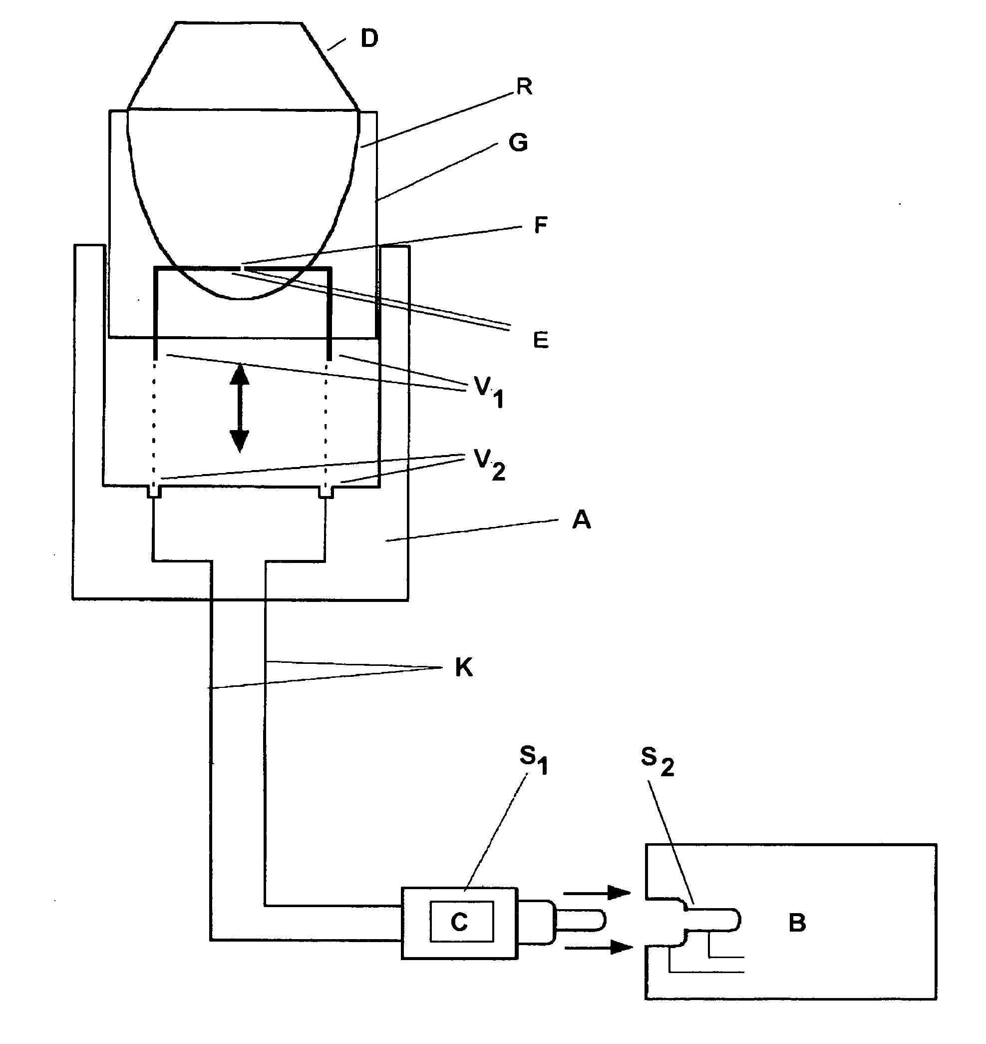
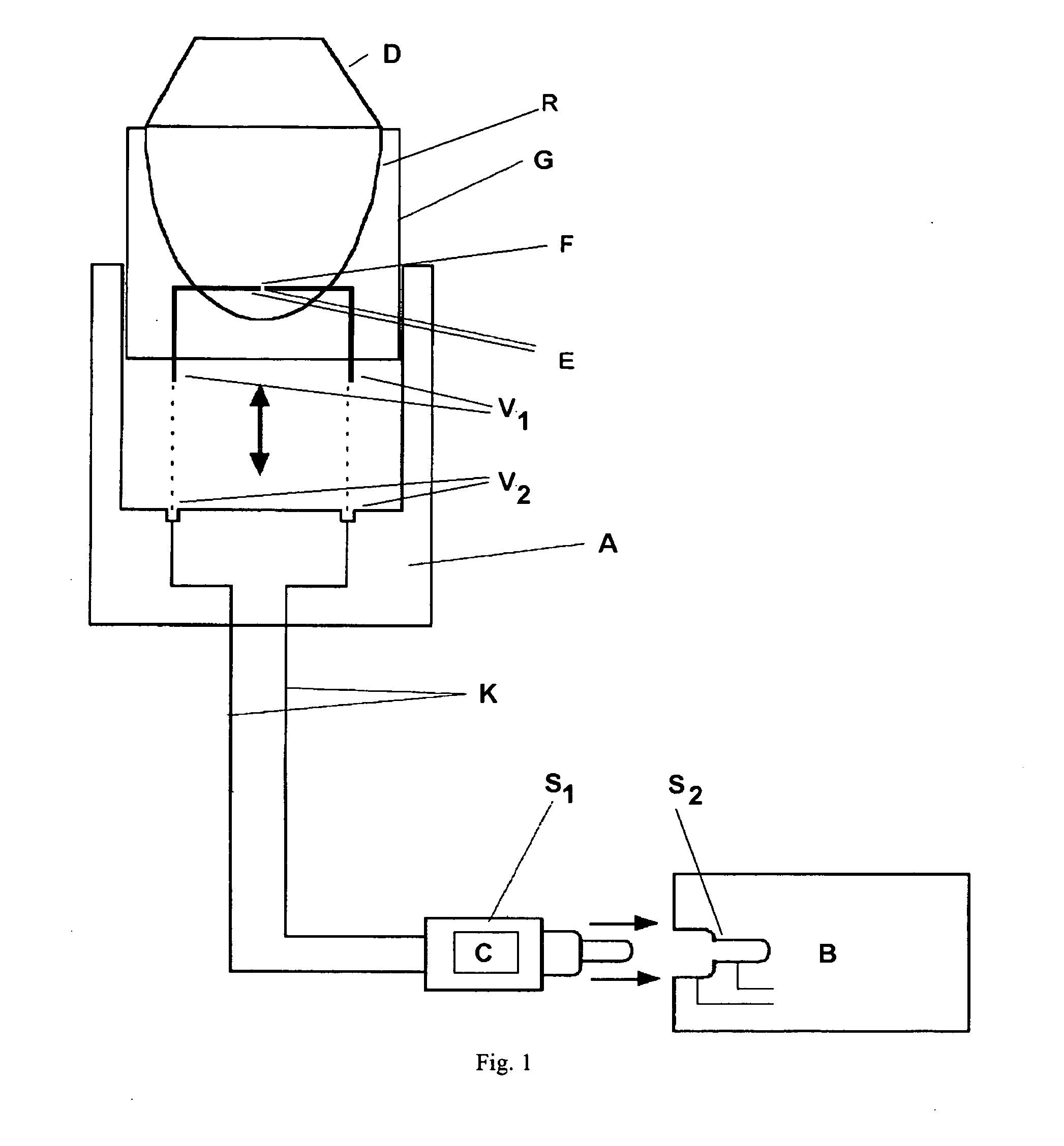
[0058] From the view according to FIG. 1, a schematic view of a therapy head according to the invention with a reflector retainer A according to the invention and a reflector R according to the invention can be seen.

[0059] The reflector R comprises two electrodes E of the spark discharge section F. Preferably, the electrodes are made from a stainless steel material. The reflector R is arranged in a housing G. The electrodes E are connected with connection elements V1. The connection elements V1 are arranged such that they are connectable to connection elements V2 of a reflector retainer A.

[0060] Corresponding to the connection elements V1 of the electrodes E, the reflector retainer A comprises connection elements V2. The connection elements V2 are connected to the basis device B by means of high voltage cables K. For example, the connection elements V1 and V2 can be implemented as a plug system or a rotation / plug system.

[0061] The connection elements V1 and V2 can also each compr...


PUM


Abstract

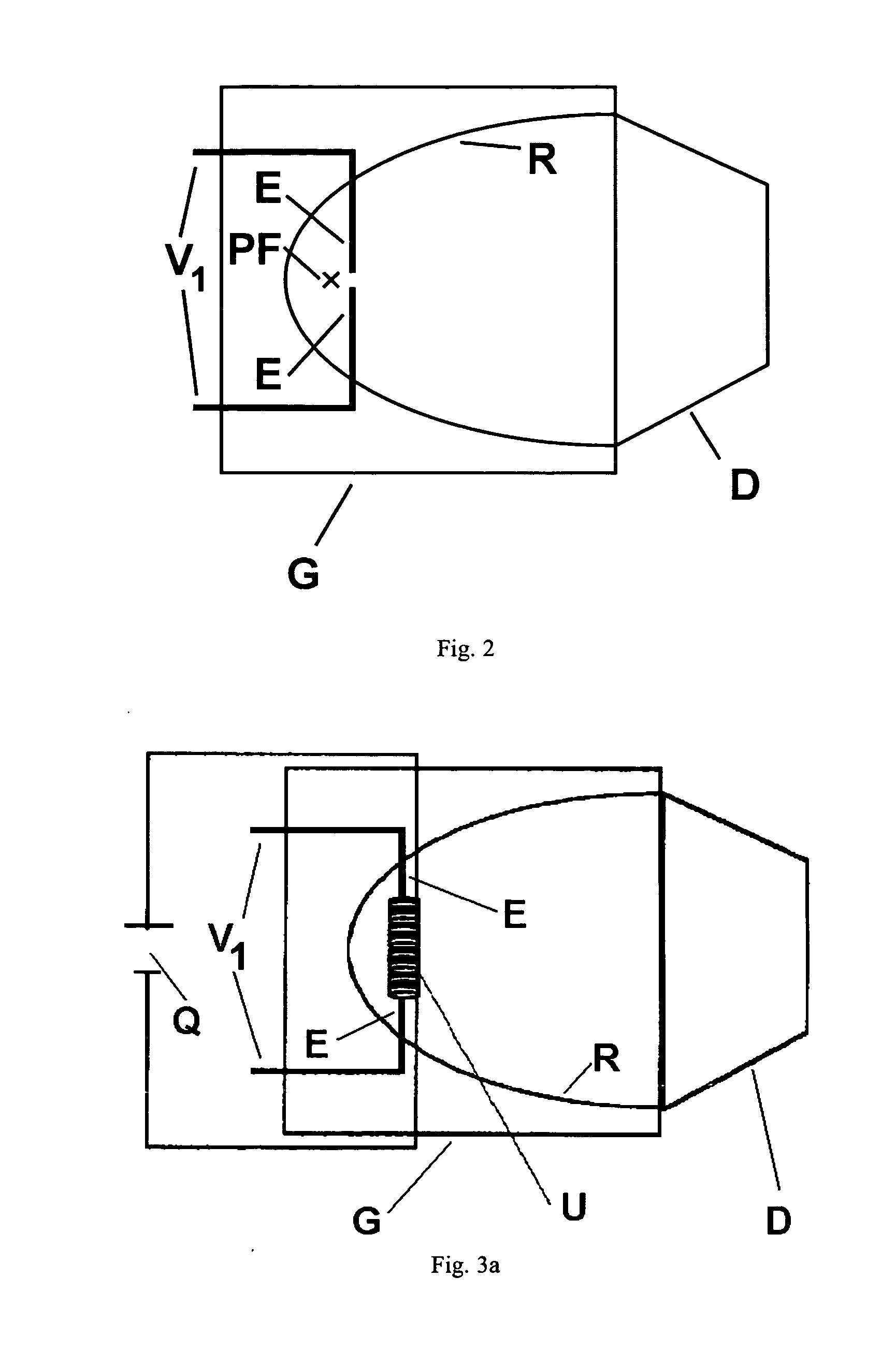
The invention relates to improvements for shock wave generators. The improvements relate on the one hand to a therapy head with a reflector and a reflector retainer, on the other hand to a field assistance device for a spark discharge section. A reflector according to the invention comprises two electrodes of a spark discharge section, wherein the reflector is made from cost-saving, corrosion-resistant, non-metallic materials, and a reflector retainer according to the invention comprises connection elements for connecting a reflector with a basis device, wherein the reflector can releasably be connected to and / or secured to the reflector retainer. The spark discharge section can be located next to a primary focus of the reflector ellipsoid to effect an extension of the target focus area. A field assistance device according to the invention for a spark discharge section is operating magnetically and allows reliable firing even for large distances of the electrodes.

Description

STATEMENT OF RELATED CASES [0001] Pursuant to 35 U.S.C. 119(a), the instant application claims priority to prior German application number 10 2006 002 418.4, filed Jan. 18, 2006. This application also claims the benefit of U.S. Provisional Application No. 60 / 759,855, filed Jan. 18, 2006. FIELD OF THE INVENTION [0002] The invention relates to improvements for shock wave generators. BACKGROUND [0003] Shock wave generators are used in numerous medical fields. The best-known field is the therapeutic and cosmetic application in the treatment for instance of calculous diseases (e.g., urolithiasis, cholelithiasis) and the treatment of scars in human and veterinary medicine. [0004] New fields of application relate to dental treatment, the treatment of arthrosis, the ablation of calcerous deposits (e.g., tendinosis calcarea), the treatment of chronic tennis or golfer elbows (so called radial or ulnar epicondylopathy), of chronic discomfort of the shoulder tendons (so called enthesopathy of t...

Claims


Application Information

Patent Timeline
IPC IPC(8): A61H1/00
CPCA61H23/008
Inventor VOSS, AXEL
Owner TISSUE REGENERATION TECH
Learn More