Support structure for a planar cooling device

a support structure and cooling device technology, applied in indirect heat exchangers, lighting and heating apparatus, instruments, etc., can solve the problems of increasing the difficulty of keeping various electronic devices cool enough for optimal performance, reducing the overall thickness of the device, and not providing an adequate solution to heat generation in these devices

Inactive Publication Date: 2007-10-18
CELSIA TECH KOREA
View PDF15 Cites 68 Cited by
  • Summary
  • Abstract
  • Description
  • Claims
  • Application Information

AI Technical Summary

Benefits of technology

[0016] In yet another aspect, the invention is a method of making a cooling device. The method entails forming a support structure by providing a flat plate, cut

Problems solved by technology

Keeping various electronic devices cool enough for optimal performance has become more challenging as the circuit density increases and many of these devices are made smaller and lighter.
With electronic devices getting more compact yet including more heat sources, the traditional methods of dealing with heat dissipation, such as open packaging or cooling fans, do not provide an adequate solution to heat generation in these devices.
The overall thickness cannot be decreased without compromising the cooling e

Method used


Image

  • Support structure for a planar cooling device
  • Support structure for a planar cooling device
  • Support structure for a planar cooling device

Examples


first embodiment

[0033]FIG. 3 is an exploded perspective view of the cooling device in accordance with the invention, FIG. 4 is a cross-sectional view of the cooling device of FIG. 3, and FIG. 5 is a close-up view of a portion of the support structure in the cooling device of FIG. 3.

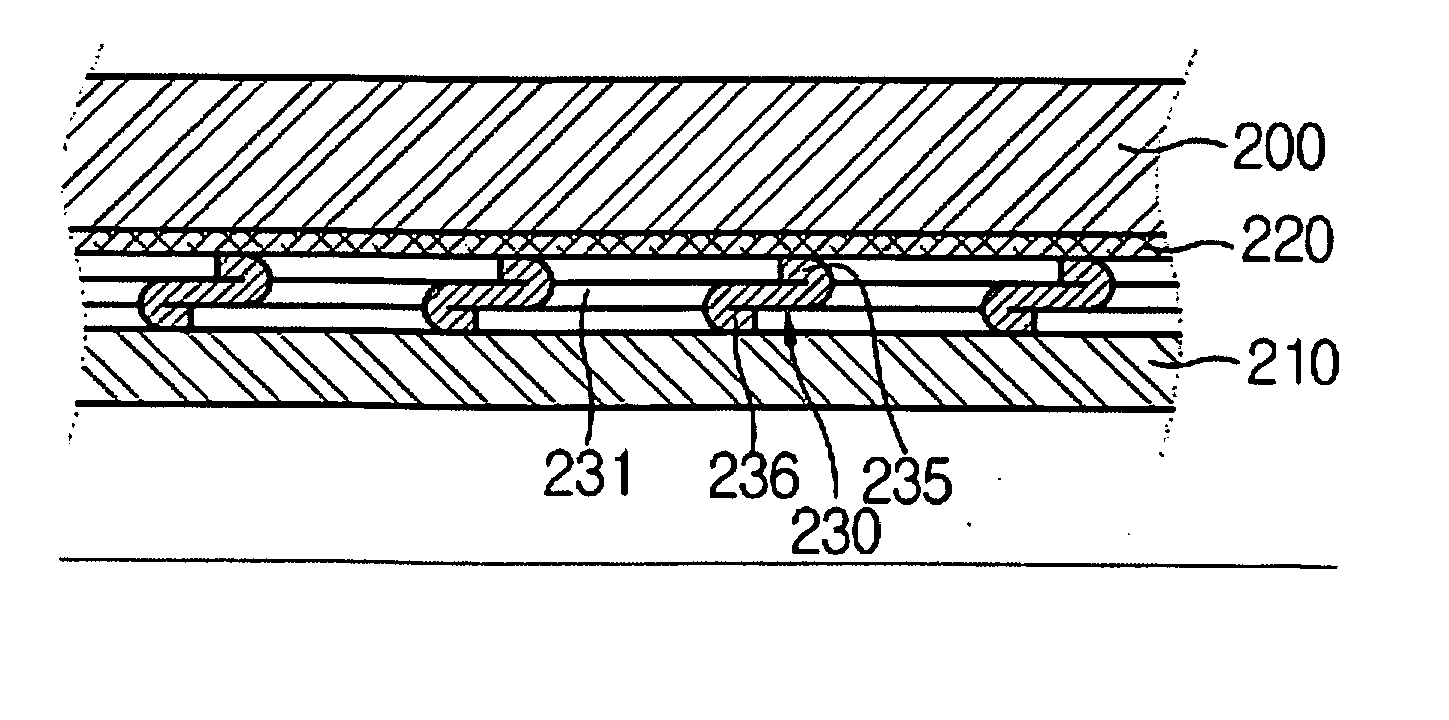
[0034] As shown in FIG. 3, the cooling device of the invention includes a casing made of a first plate 200 and a second plate 210. The first plate 200 and the second plate 210 may be combined to form an enclosed space between the two plates 200, 210. The two plates 200, 210 may be sealed together to form the enclosed space so that a coolant fluid (e.g., water, methanol, ethanol) is contained in the enclosed space. The seal may be formed around the edges so as to not intrude upon the enclosed space. Either or both of the first and second plates 200, 210 is designed so that it can be attached to a printed circuit board (PCB) or a chip. For example, the first plate 200 may have a flat surface that can easily be attached to ...

second embodiment

[0047]FIG. 8 is an exploded perspective view of the cooling device in accordance with the invention. As shown, the cooling device of the multi-wick embodiment includes the first plate 200, the second plate 210, and the support structure 330. In addition, the cooling device includes a first wick layer 220a and a second wick layer 220b positioned between the support structure 330 and one of the plates 200, 210, respectively. The support structure 330 is, therefore, located between the two wick layers 220a, 220b. Details of the support structure 330 were provided above in reference to FIG. 6. The cooling device of FIG. 8 may be made with the support structure 230 or 430 as well. The multi-wick embodiment of the cooling device works particularly well when there are two heat sources, one near each of the two plates 200, 210. In the case where there are two heat sources, the parts of the cooling device that are closest to the two heat sources act as evaporation areas, and condensation occ...

third embodiment

[0048]FIG. 9 is the cooling device in accordance with the invention. The finned-embodiment that is shown is substantially similar to the embodiment of FIG. 3 except that it has fins 213 on the lower plate 211 to increase the heat exchange surface. In this embodiment, the first plate 210 is designed so it can be positioned adjacent to a heat source. The coolant fluid evaporates on the side of the support structure 230 that is closer to the first plate 200, then expands into the side that is closer to the second plate 210 through the openings 231. Optionally, each of the fins 213 is designed with a hollow space 215 so that the coolant fluid can travel inside the fins 213 for a more effective heat dissipation. However, the fins 213 being designed to hold coolant fluid is not a requirement of the invention. The presence of the fins 213, even without the hollow spaces 215, aids heat dissipation by increasing the heat exchange surface.


PUM

PropertyMeasurementUnit
Angleaaaaaaaaaa
Shapeaaaaaaaaaa
Efficiencyaaaaaaaaaa

Abstract

A support structure for a compact planar cooling device is presented. The support structure allows the cooling device to be made with a simpler structure than most conventional cooling devices. The cooling device includes a planar casing, a wick layer, and the support structure. The support structure includes a flat plate with a portion cut out to form an opening and a spacer on the flat plate. The spacer is made by bending or folding the cut-out portion of the plate. The spacer enhances coolant circulation inside the cooling device by pushing the wick layer against the inner surface of the casing and maintaining a set distance between the support structure and the casing to allow unimpeded coolant movement. The cooling device can be made cost-effectively without compromising heat transfer efficiency.

Description

CROSS REFERENCE TO RELATED APPLICATION(S) [0001] This application claims priority from Korean Patent Application No. 10-2006-0034917 filed on Apr. 18, 2006, the content of which is incorporated by reference herein in its entirety. BACKGROUND OF THE INVENTION [0002] 1. Field of the Invention [0003] The invention relates generally to heat transfer devices and more specifically to cooling devices capable of being placed in small spaces. [0004] 2. Background Information [0005] Today, memory chips, central processing units, and embedded chips are used in numerous types of electronic devices. To ensure reliable operation of these devices, the devices have to be prevented from overheating. Keeping various electronic devices cool enough for optimal performance has become more challenging as the circuit density increases and many of these devices are made smaller and lighter. Furthermore, many consumer electronic devices today include additional heat sources such as optical display component...

Claims


Application Information

Patent Timeline
IPC IPC(8): F28D15/04
CPCF28D15/0233F28D15/046G06F1/20Y10T29/49353H01L2924/0002H01L23/427H01L2924/00H05K7/20
Inventor MEYER, GEORGE A. IVNAM, KI-BUKWACK, SUNG SIKCHOI, JAE JOON
Owner CELSIA TECH KOREA
Why Eureka
Try Eureka