Drill bit with multiple cutter geometries

a drill bit and geometrie technology, applied in the field of rotary drill bits, can solve the problems of severe reduction of rop, achieve the effect of increasing wear, effective drill bit durability and ability to drill efficiently

Inactive Publication Date: 2007-10-18
VAREL INT IND
View PDF16 Cites 49 Cited by
  • Summary
  • Abstract
  • Description
  • Claims
  • Application Information

AI Technical Summary

Benefits of technology

[0012] Embodiments of the invention are directed to a drill bit, and method of assembling same, that becomes more effective mechanically, and also gains in stability with increasing wear. The drill bit has cutting elements with multiple cutting surface geometries that are positioned so that their cutting profiles overlap, but do not completely contain or engulf one another. The different cutting surface geometries and specific overlap of the cutting elements define zones of different cutting element densities in the cutting surface and along the bit's profile. In one implementation, the overlap occurs in the middle regions o

Problems solved by technology

The overlap helps provide greater coverage for the borehole bottom, but can result in a specific wear pattern that, de

Method used


Image

  • Drill bit with multiple cutter geometries
  • Drill bit with multiple cutter geometries
  • Drill bit with multiple cutter geometries

Examples


Embodiment Construction

[0028] Following is a detailed description of the invention with reference to the drawings. It should be noted that the drawings are provided for illustrative purposes only and are not intended to be a blueprint or manufacturing drawings, nor are they drawn to any particular scale.

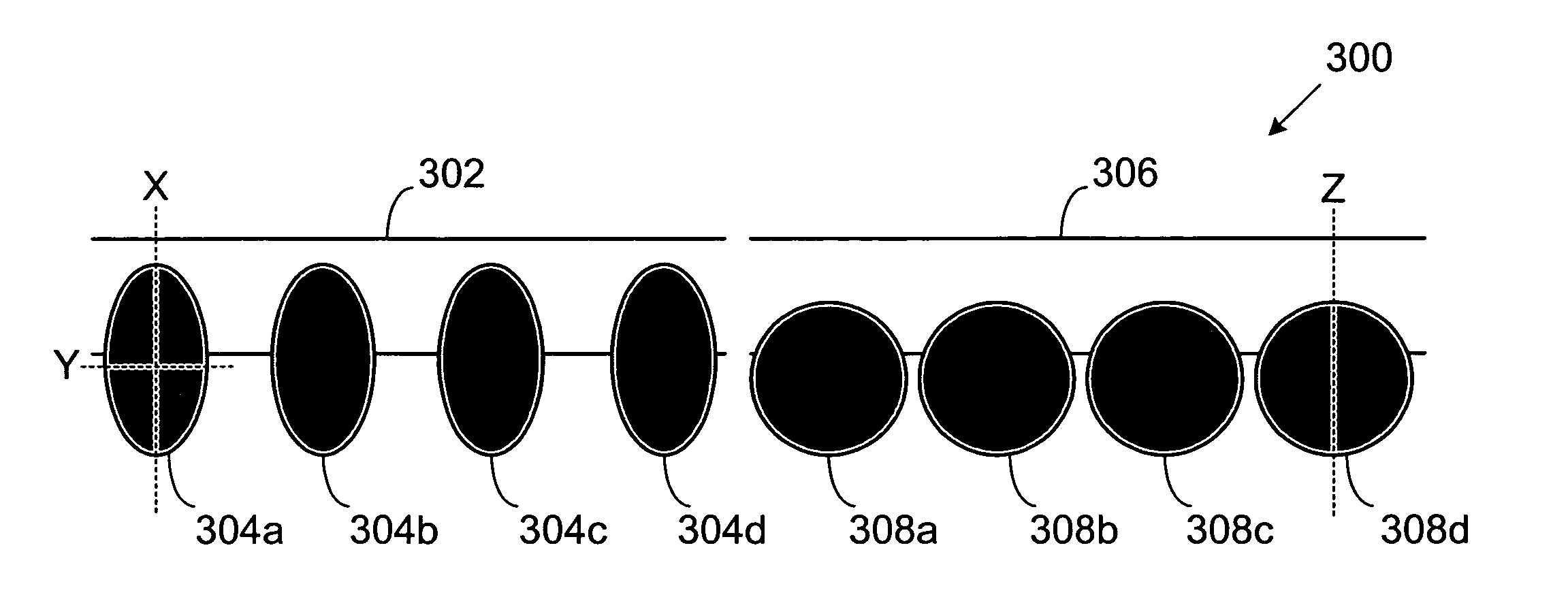
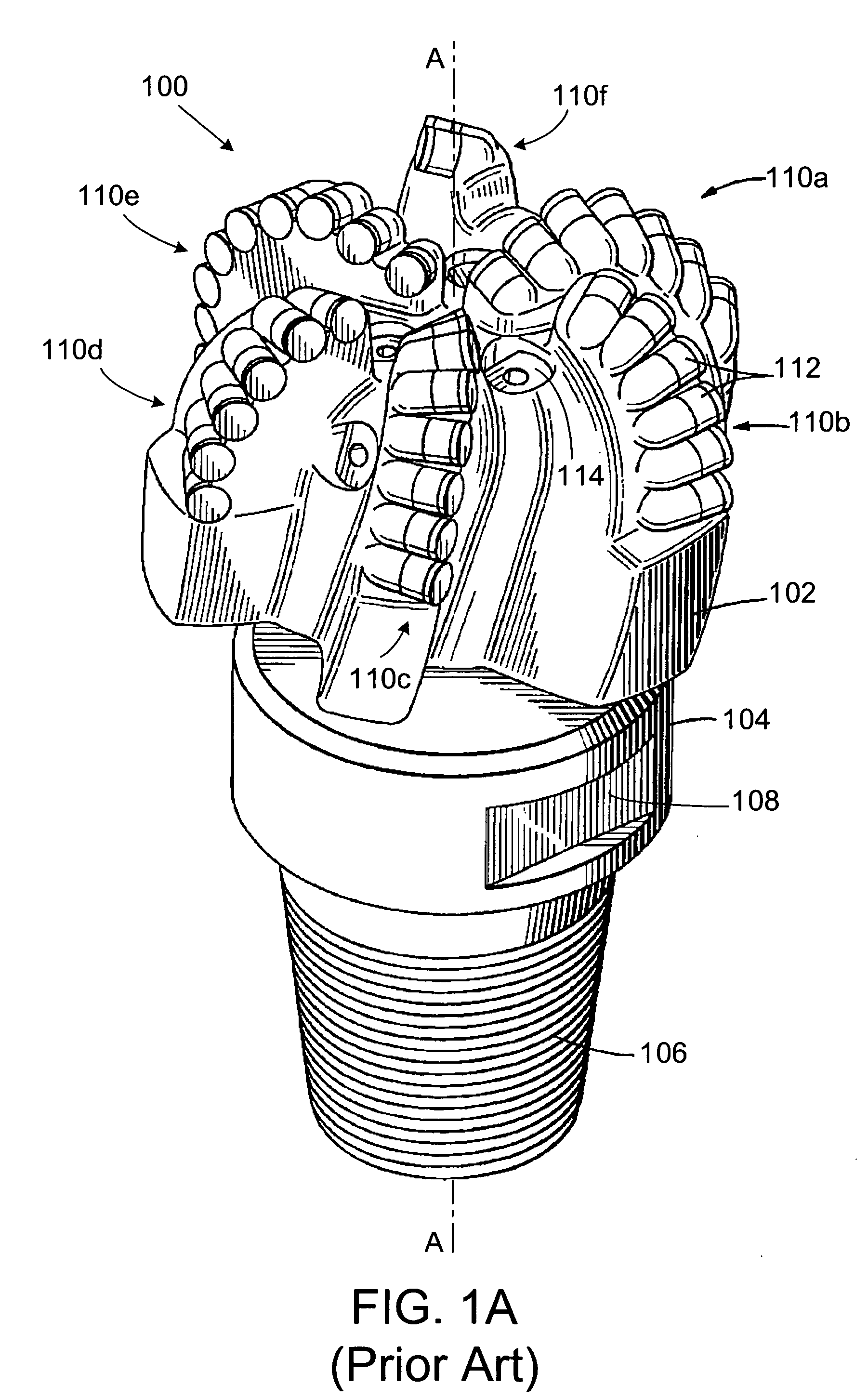
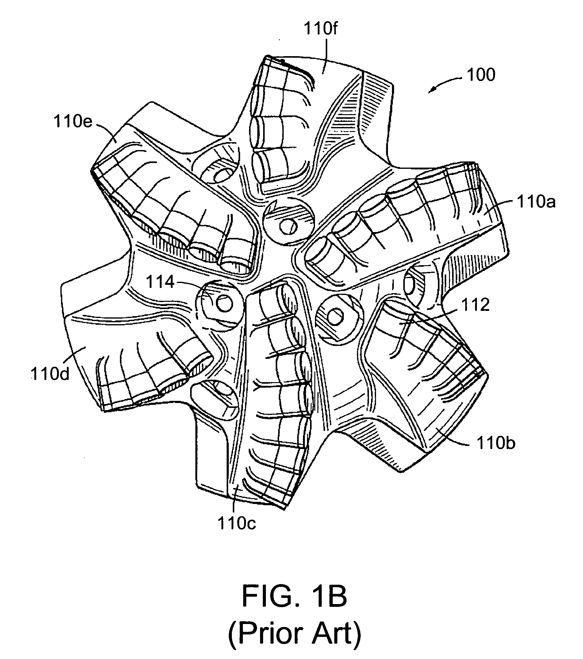
[0029] As mentioned above, existing fixed cutter drill bits have cutting elements that have identical cutting surface geometries and are arranged on the blades so that they radially overlap on the periphery of their cutting profiles. The term “geometry” refers to the size, shape, and orientation of the cutting surfaces, but not their positioning or cutting angle on the blades. For bits where each radial position is unique, the peripheral overlap creates a smooth wear pattern that can drastically reduce ROP especially in hard formations. For bits where multiple cutting elements share a common radial position, the peripheral overlaps initially locate cutter wear at the tips of the cutting elements. The resu...


PUM

PropertyMeasurementUnit
Grain sizeaaaaaaaaaa
Volumeaaaaaaaaaa
Shapeaaaaaaaaaa

Abstract

A drill bit has cutting elements with multiple cutting surface geometries that are positioned so that their cutting profiles overlap, but do not completely contain or engulf one another. The different cutting surface geometries and the specific overlap create a zone of high density in the middle regions of the cutting profiles and low density in the periphery, resulting in a cutting profile that becomes sharper with increasing wear. Such an arrangement is more effective and stable as the drill bit encounters hard and abrasive formation materials. Moreover, cutting elements with larger axial volumes may be combined with cutting elements having smaller axial volumes, resulting in an even more effective drill bit in terms of durability and ability to drill efficiently in hard and abrasive formations.

Description

FIELD OF THE INVENTION [0001] The present invention relates to rotary drill bits for rotary drilling of subterranean formations and, more specifically, to a rotary drill bit having cutting elements with multiple geometries and arranged so that the drill bit becomes more stable and mechanically more efficient with increasing wear on the cutting elements. BACKGROUND OF THE INVENTION [0002] Subsurface formation drilling to recover hydrocarbons is well known in the art. The equipment for such subsurface formation drilling typically comprises a drill string having a rotary drill bit attached thereto that is lowered into a borehole. A rotary table or similar device rotates the drill string, resulting in a corresponding rotation of the drill bit. The rotation advances the drill bit downwardly, causing it to cut through the subsurface formation (e.g., by abrasion, fracturing, and / or shearing action). Drilling fluid is pumped down a channel in the drill string and out the drill bit to cool t...

Claims


Application Information

Patent Timeline
IPC IPC(8): E21B10/36
CPCY10T29/49826E21B10/567
Inventor MENSA-WILMOT, GRAHAM
Owner VAREL INT IND
Why Eureka
Try Eureka