
Communication device and network selection method for use in same

a communication device and network selection technology, applied in the field of communication devices and network selection methods, can solve the problems of inability to take into account differences in routing process, inability to dynamically change the optimum route, and inability to flexibly select the route depending on the servi

Inactive Publication Date: 2007-10-18
NEC CORP
View PDF4 Cites 59 Cited by
  • Summary
  • Abstract
  • Description
  • Claims
  • Application Information

AI Technical Summary

Benefits of technology

[0019]That is, the communication device according to the present invention can automatically and constantly select the optimum network by dynamically changing the method of determining a route depending on the available application, the status of a service or the history of the application.
[0023]With the above-mentioned configuration and operation, the present invention has the effect that the optimum network can be selected for routing without preparing a statically generated connection profile.

Problems solved by technology

However, since a route is uniquely determined only depending on a destination IP address in this method, a route cannot be flexibly selected depending on a service.
For example, although there are differences in communication characteristics in Web browsing, downloading a file of a large capacity, and voice communications performed by a VoIP (voice over IP), the differences cannot be taken into account in performing the routing process.
However, in this method an appropriate network is selected “for each terminal device”, and a plurality of application operating in a terminal cannot select respective network.
Furthermore, in this method, the optimum route cannot be dynamically changed depending on an available service and the status of an application.
Therefore, for example, it would not be possible to change the present route to another route automatically whose use fee is cheaper than that of the present route, when an amount of data used by an application increases.
Furthermore, in the conventional routing control method, a method of selecting a route cannot be dynamically changed depending on the application, the status of a service or the history of the application.
Therefore, it would not be possible to change a route to another route dynamically when another route becomes the optimum route at the timing.

Method used


Image

  • Communication device and network selection method for use in same
  • Communication device and network selection method for use in same
  • Communication device and network selection method for use in same

Examples


embodiment 1

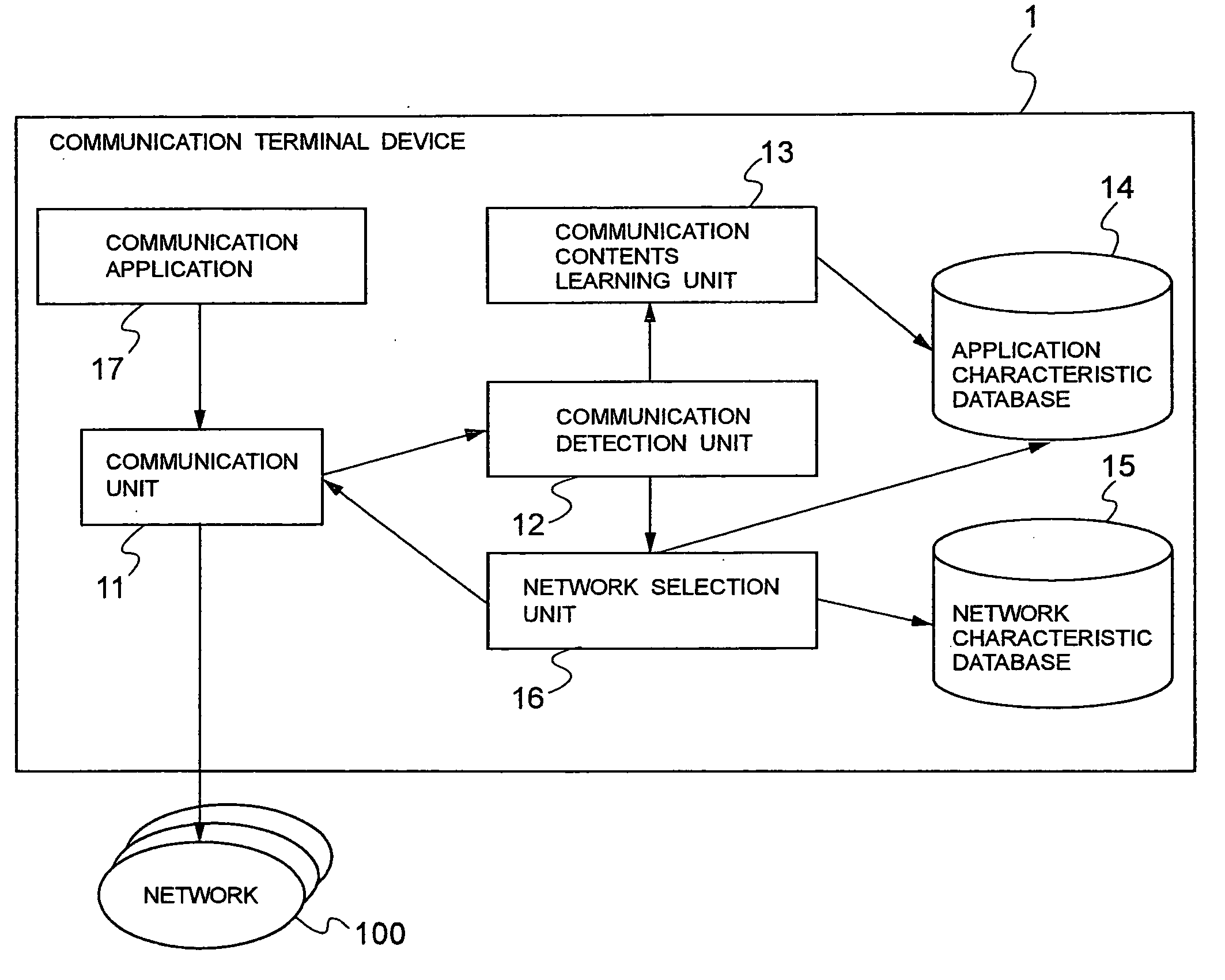
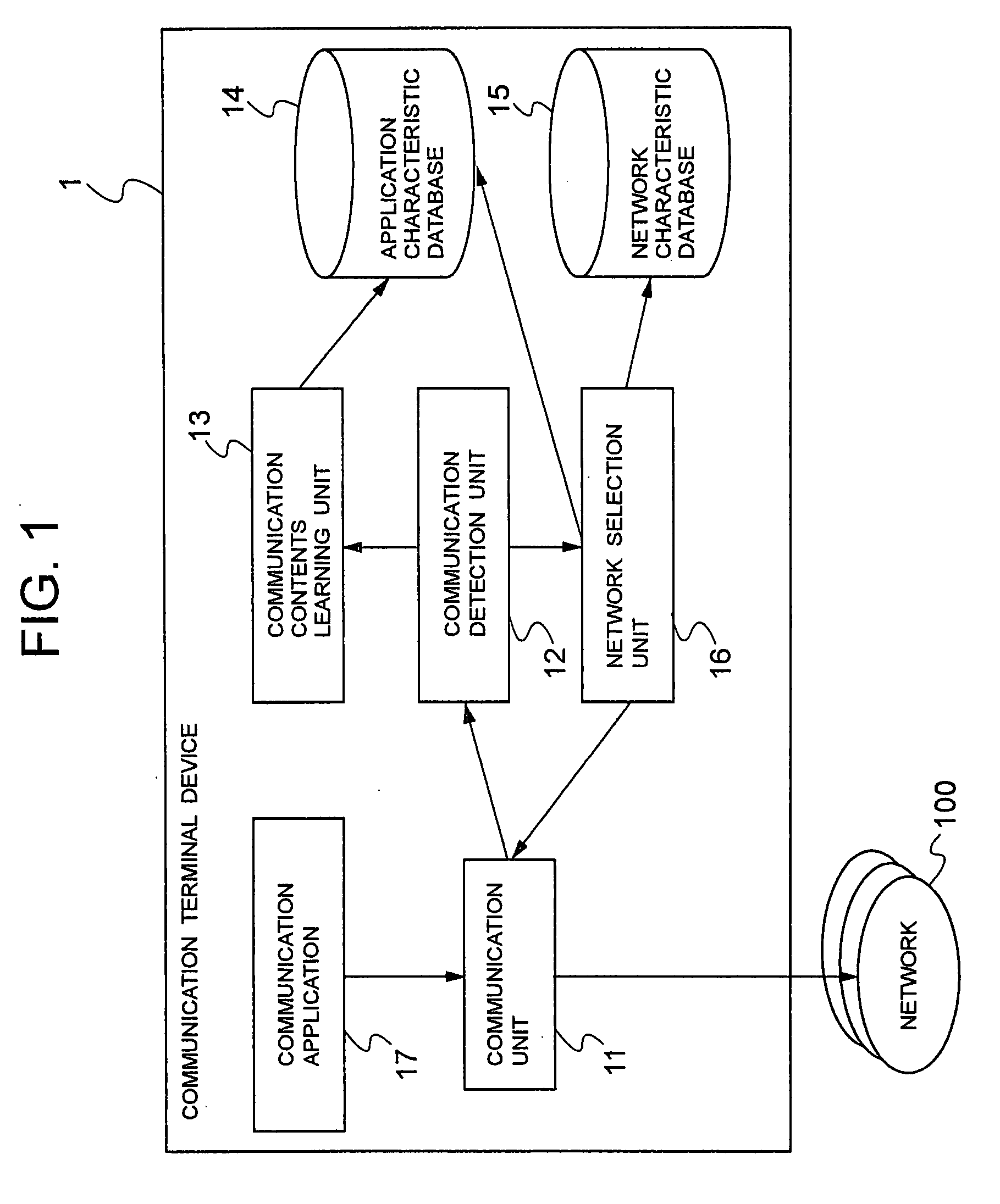
[0040]FIG. 1 is a block diagram showing the configuration of the communication terminal device according to a first embodiment of the present invention. In FIG. 1, a communication terminal device 1 is a communication device capable of receiving a network service by connection to one or more networks 100 simultaneously or by switching, and includes a communication unit 11, a communication detection unit 12, a communication contents learning unit 13, an application characteristic database 14, a network characteristic database 15, a network selection unit 16, and a communication application 17.

[0041]The type of network 100 can be various networks such as the Internet, the Intranet, a wireless LAN (local area network) spot, a domestic LAN, an in-shop LAN, etc.

[0042]The communication terminal device 1 is connected to the network 100 using the communication unit 11. At this time, a connecting medium can be, for example, a cable LAN, a wireless LAN, a public telephone network, a mobile tel...

embodiment 2

[0070]FIG. 6 is a block diagram showing the configuration of the communication terminal device according to the second embodiment of the present invention. In FIG. 6, the communication terminal device 1a according to a second embodiment of the present invention has the same configuration as the communication terminal device 1 according to the first embodiment of the present invention shown in FIG. 1 except that a user interface 18 is newly added, and the same component is assigned with the same reference numeral. The operation of the same component in the present embodiment is identical to the operation according to the first embodiment of the present invention.

[0071]The user interface 18 presents and selects a network that can be selected by a user in selecting a network, and enables a user to use it when the user amends the characteristic of an application. The user interface 18 has a display unit or the function of outputting voice as a display unit for presenting information to ...

embodiment 3

[0077]FIG. 9 is a block diagram showing the configuration of the communication terminal device according to the third embodiment of the present invention. In FIG. 9, the communication terminal device 1b according to a third embodiment of the present invention has the same configuration as the communication terminal device 1 according to the first embodiment of the present invention shown in FIG. 1 except that a position detection unit 19 is newly added, and the same component is assigned with the same reference numeral. The operation of the same component in the present embodiment is identical to the operation according to the first embodiment of the present invention.

[0078]The position detection unit 19 is a unit of obtaining the current position information of the communication terminal device 1b. Practically, there is a method of designating the current position of the device using the position information through a GPS (global positioning system) or a basic station (not shown in...


PUM


Abstract

The present invention provides a communication device which can perform a routing process by selecting the optimum network without preparing a statically generated connection profile. A communication detection unit detects the start of communication by a communication unit, and activates a network selection unit. The network selection unit checks an application characteristic database on the basis of a parameter from the communication detection unit, and refers to a corresponding application characteristic. The network selection unit refers to a network characteristic database, and selects the optimum network. The communication unit connects the optimum network on the basis of the selection result. When the communication application starts communication, the communication detection unit notifies the communication contents learning unit of the communication contents. The communication contents learning unit analyzes the communication contents and acquires statistics, and updates the information about the application characteristic database.

Description

BACKGROUND OF THE INVENTION[0001]1. Field of the Invention[0002]The present invention relates to a communication device, and a network selection method for use in the device, and more specifically, to a method for controlling routing in connection to a plurality of networks in various communication methods in a communication device.[0003]2. Description of the Prior Art[0004]Recently, with an increasing use of a wireless network such as a mobile telephone network, a wireless LAN (local area network), etc., there is a greater use of connecting a mobile terminal device to various networks.[0005]For example, a communication system includes a cellular network, a wireless LAN, a PHS (personal handyphone system) connection, Bluetooth®, etc. The networks to be connected are a cellular network, the Internet, an in-house intranet, a domestic LAN, and a VPN (virtual private network) connection to them.[0006]When connections are simultaneously performed using an IP (Internet protocol) to a plur...

Claims


Application Information

Patent Timeline
IPC IPC(8): H04J1/16H04L45/85
CPCH04W48/18H04L12/5692
Inventor MURAKAMI, TAKUYAOKUYAMA, YOSHIAKI
Owner NEC CORP
Learn More