Strain measuring device

a technology of strain measurement and measuring device, which is applied in the direction of force measurement, force measurement apparatus, force/torque/work measurement, etc., can solve the problems of difficult handling during manufacture, nonlinear, and semiconductor strain gages that introduce almost as many problems, so as to improve linearity and temperature transient behavior.

Inactive Publication Date: 2007-10-25
METTLER TOLEDO INC
View PDF2 Cites 3 Cited by
  • Summary
  • Abstract
  • Description
  • Claims
  • Application Information

AI Technical Summary

Benefits of technology

[0014] An advantage of the exemplary embodiment of the present invention is to provide a means for improving the linearity in a column load cell while retaining the column load cell's favorable temperature transient behavior.
[0019] Other advantages of the invention may be achieved by a device for measuring the magnitude of a linear tensile force, the device having improved linearity and temperature transient behavior. Such a device would incorporate a column load cell of an embodiment described above, the connectors of which will be connected to an end of a pair of roller chain portions, with the opposite ends of the roller chain portions receiving the tensile force through attachment to a source of the tensile force.

Problems solved by technology

Unfortunately, if the output of a real column cell is plotted against load, the plotted curve is not straight (nonlinear).
The semiconductor strain gages introduce almost as many problems as they solve, however.
They are expensive, difficult to handle during manufacture and prone to large resistance changes with temperature.
However, both computers and active circuits restrict the user in terms of either the power requirements, signal outputs, or both.
However, if the tensile and compressive strains are unequal in absolute value, then the Wheatstone bridge will give an output which is nonlinear even if the strains themselves are perfectly linear.
Mathematical modeling of the diameter change and the Wheatstone bridge nonlinearities is unable to predict a total cell output which matches experimental measurements.
These effects are simple and easy to quantify, yet they do not explain the nonlinear output of real load cells.
Otherwise identical manufacturing methods routinely produce cells having a variation in linearity in the aforementioned +500 to +1000 ppm range, but such a large change variation is also unexplained using the diameter change and Wheatstone bridge nonlinearities.
However, if the absolute values of the strains on the four arms of the bridge are unequal, then the output of the Wheatstone bridge is much more nonlinear.
Unfortunately, this device exhibits such poor behavior in the presence of temperature changes that it isn't practical for commercial load cells.
The primary cause of its temperature problems is that the tension and compression gages are usually not close to each other and are often mounted on metals of different thicknesses, so that the temperatures of the tension and compression gages are usually unequal.
The requirement for shear loading also places significant demands on their mounting: the mounting must be capable of sustaining the moments applied during shear loading.
Their size transverse to the loading direction and the mounting requirements often make them an unattractive option compared to column load cells.

Method used


Image

  • Strain measuring device
  • Strain measuring device
  • Strain measuring device

Examples


Embodiment Construction

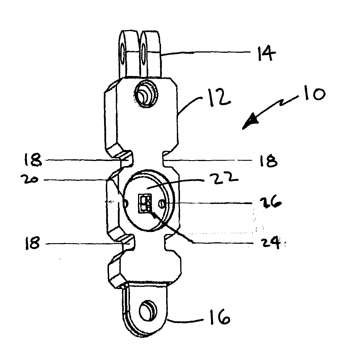
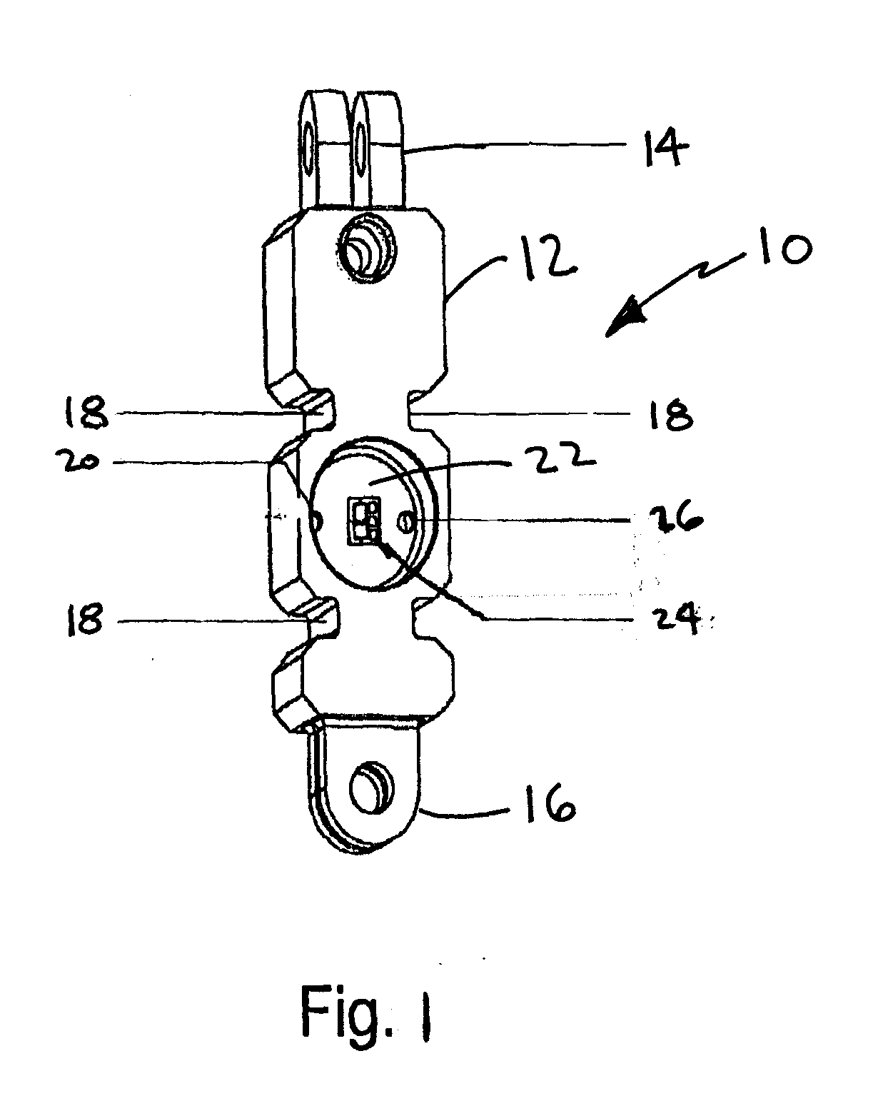
[0023]FIG. 1 shows an exemplary embodiment of a load cell 10 of the present invention. The load cell 10 is characterized by an elongate body 12, each end of which is adapted with a connector for receiving a roller chain. The notable feature of the connectors is not that their similarities, but is their difference. The first connector 14 is oriented to receive a roller chain portion in which the parallel pins that connect the links are oriented in a left to right axis across the plane of the drawing. The second connector 16 is oriented to receive a roller chain portion in which the parallel pins that connect the links are oriented in an axis coming normally out of the plane of the drawing. Described in another way, the load cell 10 and the connectors 14,16 at the ends thereof are in mutually orthogonal orientation. The load cell 10 is also characterized by four notches 18 that represent removed material from what would be an otherwise generally rectangular cross-section.

[0024] Mount...


PUM

PropertyMeasurementUnit
Poisson's ratioaaaaaaaaaa
tensile forceaaaaaaaaaa
temperature transientaaaaaaaaaa

Abstract

A tensile force measuring device provides improved linearity and temperature transient behavior. A column load cell (10) in the device is connected at its ends to a first and a second roller chain portion (34, 36), which are in turn connected to the tensile force, to dispose the column load cell to the tensile force between the chain portions. The roller chain portions are connected to the load cell in mutually perpendicular orientation. The load cell has notches (18) formed in the side thereof to equalize the strain thereupon when tensile load is applied. Longitudinal and transverse strain gages (20) are positioned longitudinally intermediate to the notches, and may be on a gaging web (22).

Description

TECHNICAL FIELD [0001] The present invention relates to strain measuring devices and more particularly to a load cell that provides improved linearity and temperature transient behavior. More particularly, the invention relates to a strain measuring device having a column load cell positioned between a pair of perpendicularly-oriented roller chain portions BACKGROUND OF THE ART [0002] Tensile and compressive forces today are measured with a wide variety of technologies. Most of the lowest cost designs use strain gages and many designs exist. One of the oldest and most popular strain gage designs is the column load cell. Columns usually have a long, slender elastic member loaded along its long axis in either tension or compression. Strain gages are affixed to the elastic member in such a way that both the longitudinal and transverse strains can be measured and combined to produce a total output proportional to the load. These devices usually assume that strain gages perfectly measure...

Claims


Application Information

Patent Timeline
Patent Type & Authority Applications(United States)
IPC IPC(8): G01L1/22
CPCG01L5/101
Inventor SCOTT, JONLEAHY, TOMMARIANI, PHILIP
Owner METTLER TOLEDO INC
Why Eureka
Try Eureka