Twin needle valve dual mode injector

a dual-mode, fuel injection technology, applied in the direction of machines/engines, mechanical equipment, electric control, etc., can solve the problems of out-perform fuel injection systems, and engines operating in hcci mode. low output of undesirable emissions

Active Publication Date: 2007-10-25
CATERPILLAR INC
View PDF20 Cites 62 Cited by
  • Summary
  • Abstract
  • Description
  • Claims
  • Application Information

AI Technical Summary

Benefits of technology

[0007] In another aspect, the present disclosure is directed to a fuel injection system having a common fuel rail containing pressurized fuel, at least one control valve fluidly connected to the common fuel rail, and at least one fuel injector fluidly connected to said common fuel rail. The fuel injector includes an injector body having a first nozzle and a second nozzle, with the first nozzle being configured to produce a first fuel injection spray pattern and the second nozzle being configured to produce a second fuel injection spray pattern different from the first fuel injection spray pattern. Furthermore, each fuel injector may include a first needle valve member and a second needle valve member, the second valve needle member being spaced from, but adjacent to the first needle valve member.
[0008] In yet another aspect, the present disclosure is directed to a method of injecting fuel. The method includes injecting fuel through a first nozzle at least in part by moving a first needle valve member by reducing fuel pressure in a first control chamber within an injector body while maintaining fuel pressure in the remainder of the injector body. The method also includes injecting fuel through a second nozzle at least in part by moving a second needle valve member by reducing fuel pressure in a second control chamber within the injector body while maintaining fuel pressure in the remainder of the injector body. The second needle valve member being spaced from, but adjacent to the first needle valve member.

Problems solved by technology

Therefore, fuel injection systems with a variety of different capabilities can generally out-perform fuel injection systems with narrower capability ranges, at least in their ability to reduce undesirable emissions.
Engines operating in an HCCI mode have shown relatively low outputs of undesirable emissions.
Although an HCCI strategy appears promising, it is not without drawbacks.
Also, it may be difficult to control ignition timing in engines operating with an HCCI strategy.
Thus, at this time, a pure HCCI strategy is not viable for most commercial engine applications with conventional power density requirements.
Although such a dual system appears viable, the high expense and complexity brought by two complete injection systems renders it commercially challenged.
A single fuel injector is generally not compatible with performing both HCCI and conventional injections because different spray patterns are often desirable and sometimes necessitated.
Providing a structure in a single fuel injector that is capable of injecting fuel in two different spray patterns, while maintaining the ability to mass produce the fuel injector and retain consistent results, has been problematic and elusive.

Method used


Image

  • Twin needle valve dual mode injector
  • Twin needle valve dual mode injector
  • Twin needle valve dual mode injector

Examples


Embodiment Construction

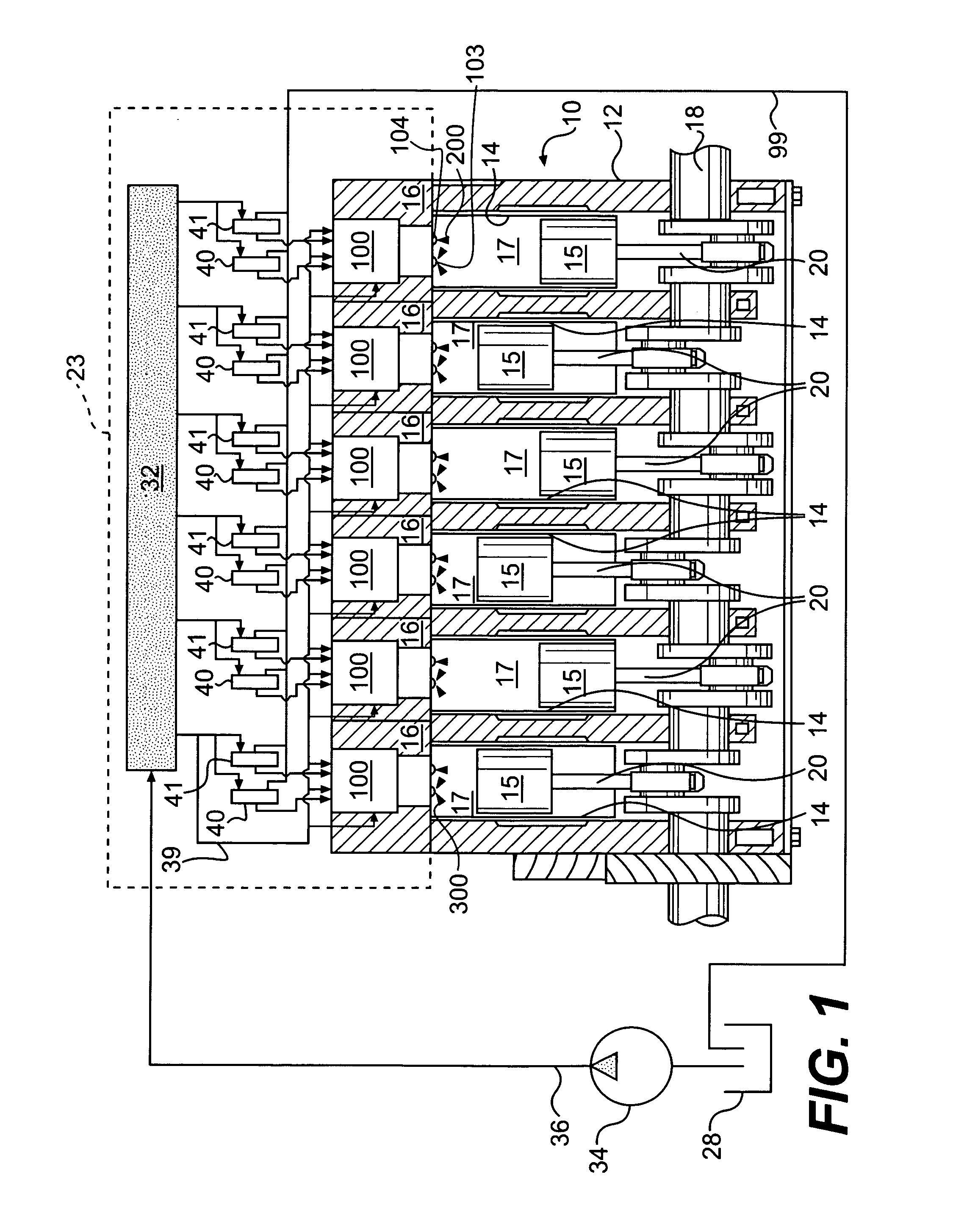
[0014] Referring to FIG. 1, there is illustrated an embodiment of a fuel injection system 23 in accordance with the present disclosure. For discussion purposes only, fuel injection system 23 is described in connection with an exemplary engine 10. For the purposes of this disclosure, engine 10 is depicted and described as a four-stroke diesel engine. One skilled in the art will recognize, however, that engine 10 may be any other type of internal combustion engine, such as, for example, a gasoline or gaseous fuel driven engine.

[0015] In the illustrated embodiment, engine 10 includes an engine block 12 that defines a plurality of cylinders 14, each having a reciprocating piston 15 slidably disposed therein. Furthermore, engine 10 may include a cylinder head 16 associated with each cylinder 14. Cylinder 14, piston 15, and cylinder head 16 cooperate together to form a combustion chamber 17. Although the exemplary engine 10 is depicted as including six combustion chambers 17, one skilled...


PUM


Abstract

A fuel injector having an injector body defining a hollow interior configured to receive pressurized fuel, a first nozzle configured for providing a first fuel spray pattern, and a second nozzle configured for providing a second fuel spray pattern different from the first fuel spray pattern. The first and second nozzles may be configured to inject fuel supplied from a common source into a combustion space. The fuel injector may further include first and second needle valve members corresponding to the first and second nozzles, respectively. The first and second needle valve members may be positioned within the hollow interior of the injector body, with the second needle valve member being spaced from, but adjacent to the first needle valve member.

Description

TECHNICAL FIELD [0001] The present disclosure relates generally to dual mode fuel injection systems and, more particularly, to a fuel injector with the ability to produce two different spray patterns via independently controlled, adjacent needle valve members. BACKGROUND [0002] Over the years, engineers have been challenged to devise a number of different solutions toward the goal of a cleaner burning engine, such as, for example, a diesel engine. Experience has taught that various injection timings, quantities, and rates have a variety of different desirable results over the complete operating range of a given engine. Therefore, fuel injection systems with a variety of different capabilities can generally out-perform fuel injection systems with narrower capability ranges, at least in their ability to reduce undesirable emissions. For instance, the leap from cam control to electronic control in fuel injection systems has permitted substantially lower emissions in several categories,...

Claims


Application Information

Patent Timeline
Patent Type & Authority Applications(United States)
IPC IPC(8): F02D1/06
CPCF02D41/401F02M2200/44F02M47/027F02M45/086
Inventor GIBSON, DENNIS HENDERSON
Owner CATERPILLAR INC
Why Eureka
Try Eureka