Method of manufacturing a solenoidal magnet

Inactive Publication Date: 2007-10-25
SIEMENS PLC
View PDF11 Cites 29 Cited by
  • Summary
  • Abstract
  • Description
  • Claims
  • Application Information

AI Technical Summary

Benefits of technology

[0009] An object of the present invention is to alleviate at least some of the problems of the prior art described above, and to provide a relatively inexpensive and lightwei

Problems solved by technology

Superconducting magnets may quench due to even a small amount of movement of even one turn of the coil.
These requirements combine to render the productio

Method used


Image

  • Method of manufacturing a solenoidal magnet
  • Method of manufacturing a solenoidal magnet
  • Method of manufacturing a solenoidal magnet

Examples


Example

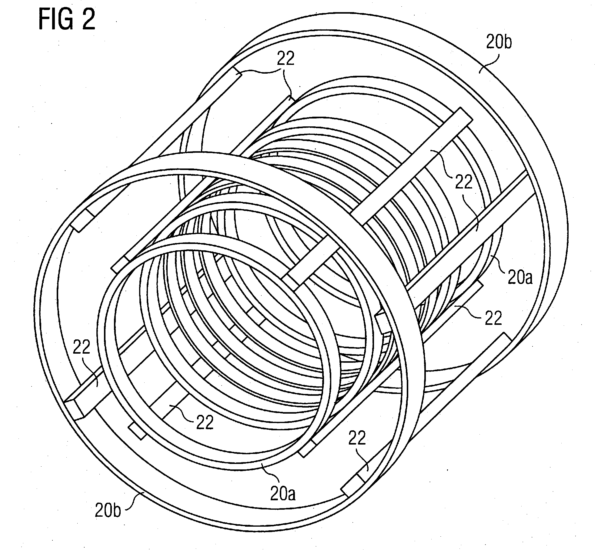
[0024]FIG. 2 shows an overall perspective view of an assembly of coils 20 and staves 22 according to an embodiment of the present invention. The coils are divided into inner coils 20a and outer coils 20b.

[0025]FIG. 3 shows an axial view of an assembly of coils 20 and staves 22 according to an embodiment of the present invention. In FIG. 3, staves 22 are shown only partially surrounding the inner coils 20a. However, it should be understood that the staves are present around the entire perimeter of the inner coils 20a in the embodiment illustrated. The staves 22 need not be contiguous around the entire perimeter of the coils 20a, as illustrated, but may be symmetrically spaced at intervals. However, the staves 22 should be sufficient in number and strength to ensure that the coils 20 are accurately and rigidly positioned, sufficiently to withstand the forces placed on the coils.

[0026] Outer coils 20b are retained in a coaxial alignment with inner coils 20a. FIG. 4 illustrates one ex...


PUM

PropertyMeasurementUnit
Diameteraaaaaaaaaa
Structureaaaaaaaaaa
Mechanical propertiesaaaaaaaaaa

Abstract

A method of manufacturing a solenoidal magnet structure, includes the step of providing a collapsible accurate mold in which to wind the coils winding wire into defined positions in the mold, placing a mechanical support structure over the coils so wound, impregnating the coils and the mechanical support structure with a thermosetting resin, allowing the thermosetting resin to harden, and collapsing the mold and removing the resultant solenoidal magnet structure formed by the resin impregnated coils and the mechanical support structure from the mold as a single solid piece.

Description

BACKGROUND OF THE INVENTION [0001] 1. Field of the Invention [0002] The present invention relates to a method of manufacture of solenoidal magnet coils, and to solenoidal magnet coils themselves. In particular, it relates to such coils for generating high strength magnetic fields, which may be applied in systems such as nuclear magnetic resonance (NMR) or magnetic resonance imaging (MRI). [0003] 2. Description of the Prior Art [0004]FIGS. 1A-1B illustrate cross-sectional and axial sectional views, respectively, of a conventional solenoidal magnet arrangement for a nuclear magnetic resonance (NMR) or magnetic resonance imaging (MRI) system. A number of coils of superconducting wire are wound onto a former 1. The resulting assembly is housed inside a cryogen vessel 2 which is at least partly filled with a liquid cryogen 2a at its boiling point. The coils are thereby held at a temperature below their critical point. [0005] The former 1 is typically constructed of aluminum, which is mac...

Claims


Application Information

Patent Timeline
IPC IPC(8): H01F6/00
CPCG01R33/3802Y10T29/49156G01R33/381G01R33/3815G01R33/421H01F6/06H01F27/327H01F41/048H01F41/127Y10T29/49172Y10T29/4902Y10T29/49073Y10T29/49155Y10T29/49071Y10T29/49014G01R33/3804H01F6/04H01F41/00H01F41/005
Inventor CALVERT, SIMONNOYS, JONATHANTHOMAS, ADRIAN
Owner SIEMENS PLC
Why Eureka
Try Eureka