Zoom lens systems with wavefront coding

a technology of zoom lens and wavefront, applied in the direction of optical elements, instruments, optical radiation measurement, etc., can solve the problems of limiting imaging performance, aberration, and inability to achieve changes in imaging system

Active Publication Date: 2007-10-25
OMNIVISION TECH INC
View PDF53 Cites 46 Cited by
  • Summary
  • Abstract
  • Description
  • Claims
  • Application Information

AI Technical Summary

Benefits of technology

[0009] The present disclosure provides a zoom lens system for imaging incoming rays over a range of ray angles. The incoming rays are characterized by at least phase. The zoom lens system includes an optical axis and is characterized by a plurality of modulation transfer functions (MTFs) corresponding at least to the range of ray angles. The zoom lens system includes an optical group disposed along the optical axis, including at least one variable optical element t...

Problems solved by technology

Modern zoom lens systems differ from traditional zoom lens systems in that changes in the imaging system are not achieved through motion of optical elements along an optical axis.
However, modern zoom lens systems that vary through changes in optical properties of one or more optical elements may introduce aberrations that act to limit imaging performance.
These aberrations may worsen as the number of optical elements in the imaging system decreases.
Aberrations that may limit the performance of these modern zoom systems ...

Method used


Image

  • Zoom lens systems with wavefront coding
  • Zoom lens systems with wavefront coding
  • Zoom lens systems with wavefront coding

Examples


Embodiment Construction

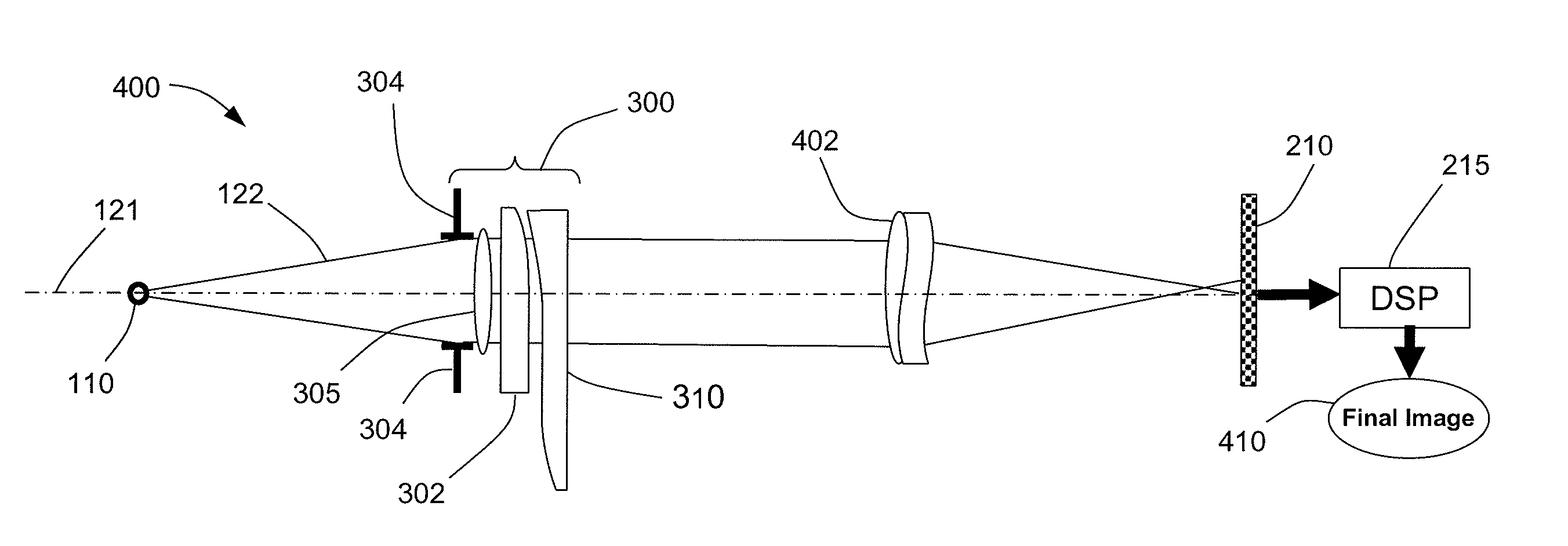
[0047] In the present disclosure, “zoom lens system” and “zoom imaging system” are used interchangeably, and “variable optical element” is intended to encompass optical elements with optical properties (such as, but not limited to, focal length, transmittance, and refractive index) that are modifiable by using techniques such as (but not limited to) application of voltage and / or pressure to one or more of the optical elements, and translation and / or rotation of one or more of the optical elements.

[0048] The use of certain aspheric optics and signal processing may provide improvements to modern zoom lens systems by mitigating certain limitations. The present disclosure concerns the use of certain aspheric optics to improve the performance, cost, and size of modern zoom lens imaging systems. Such optics and signal processing of the detected blurred images, may reduce or eliminate the effects of certain aberrations. Systems utilizing such aspheric optics and signal processing for wave...


PUM


Abstract

Zoom lens systems and methods for imaging incoming rays over a range of ray angles are disclosed. The incoming rays are characterized by at least phase. The zoom lens system includes an optical axis and is characterized by a plurality of modulation transfer functions (MTFs) corresponding at least to the range of ray angles. The zoom lens system includes an optical group disposed along the optical axis, including at least one variable optical element that has a variable focal length selectable between at least two distinct focal length values. The optical group also includes a wavefront coding element. The wavefront coding element alters at least the phase of the incoming rays, such that the plurality of MTFs corresponding to the range of ray angles, for each one of the two distinct focal length values, are less sensitive to misfocus-like aberrations than a corresponding system without the wavefront coding element.

Description

CROSS-REFERENCE TO RELATED APPLICATIONS [0001] This application claims the benefit of priority to U.S. Provisional Patent Application No. 60 / 779,712 filed 6 Mar. 2006 and entitled “Zoom Lens Systems With Wavefront Coding”, which is expressly incorporated herein by reference in its entirety.BACKGROUND OF THE INVENTION [0002] Modern zoom lens systems differ from traditional zoom lens systems in that changes in the imaging system are not achieved through motion of optical elements along an optical axis. Rather, the optical properties of particular optical elements in modern zoom systems change through application of voltage, pressure, translation or rotations in planes that are not parallel to the optical axis. One example of the use of variable optical elements in a modern zoom lens system is replacing one lens in the traditional zoom lens system with a variable optical lens at the same physical location. [0003] However, modern zoom lens systems that vary through changes in optical pr...

Claims


Application Information

Patent Timeline
IPC IPC(8): G02B15/14G02B13/18G02B15/04
CPCG02B13/12G02B15/14G02B27/52G02B27/46G02B27/0025G02B15/04G02B13/00G02B15/00G02B27/00
Inventor DOWSKI, EDWARD RAYMOND JR.TACHIHARA, SATORUCORMACK, ROBERT H.
Owner OMNIVISION TECH INC
Why Eureka
Try Eureka