Weld Testing Apparatus and Method for Nozzles

a technology of weld testing and nozzles, applied in the direction of manufacturing tools, instruments, nuclear elements, etc., can solve the problems of increasing weight, reducing the service life of nozzles,

Active Publication Date: 2007-10-25
CB CANADA ACQUISITION INC
View PDF12 Cites 5 Cited by
  • Summary
  • Abstract
  • Description
  • Claims
  • Application Information

AI Technical Summary

Benefits of technology

[0022] one or more ports for filling and pressurizing the sealed area.

Problems solved by technology

This is particularly the case when handling potentially hazardous (i.e. flammable) or toxic materials.
However, a particular problem is encountered when attempting to test the integrity of welds used in joining a nozzle to a pipe or vessel.
Further, since the tool must be sized with respect to the diameter of the pipe being tested, the resulting weight of a tool for large diameter equipment renders the tool very difficult to install and use.
This reference also does not teach a tool that can be used on a vessel nozzle and includes the same deficiency of increased weight mentioned above in that a tool for larger diameter pipes
Although this apparatus provides an accurate and efficient means of testing welds on nozzles, the size and weight of the apparatus makes it inconvenient for use on large nozzles.
Further, by sealing off the larger nozzle openings, the prior art devices also block the quickest means of ingress and egress for the technicians, which could pose a safety hazard.

Method used


Image

  • Weld Testing Apparatus and Method for Nozzles
  • Weld Testing Apparatus and Method for Nozzles
  • Weld Testing Apparatus and Method for Nozzles

Examples


Embodiment Construction

[0051] Throughout the description of the invention the following terms will be assumed to have the following associated meanings:

[0052]“Vessel ”—will be understood to mean any equipment or apparatus to which a nozzle is attached. As such, the term “vessel” will include vessels per se, pipes, drums, and any other similar equipment. It will be understood that the term “vessel” is used herein simply as a convenient way to encompass all such equipment or apparatus.

[0053]“Annular”—this term is used to describe a body having at least one outer diameter and at least one inner diameter. Thus, an “annular tube” will be assumed to be a hollow tube with an inner and outer diameter. An “annular disc ” will be assumed to be an object having an outer diameter and a central aperture thereby providing an inner diameter.

[0054]“Disc”—this term will be used to denote a generally two dimensional circular object as well as other “discs” including a circumferential flange etc.

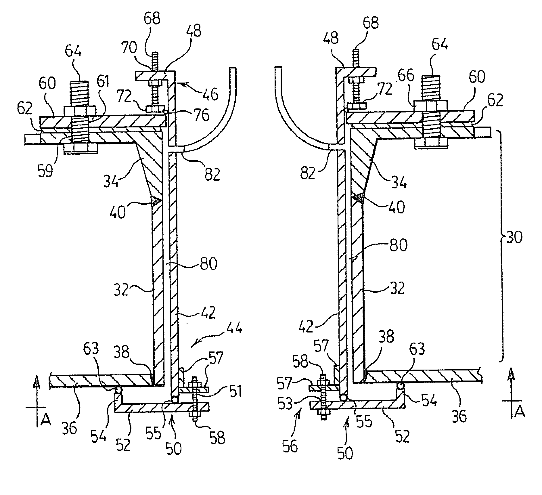
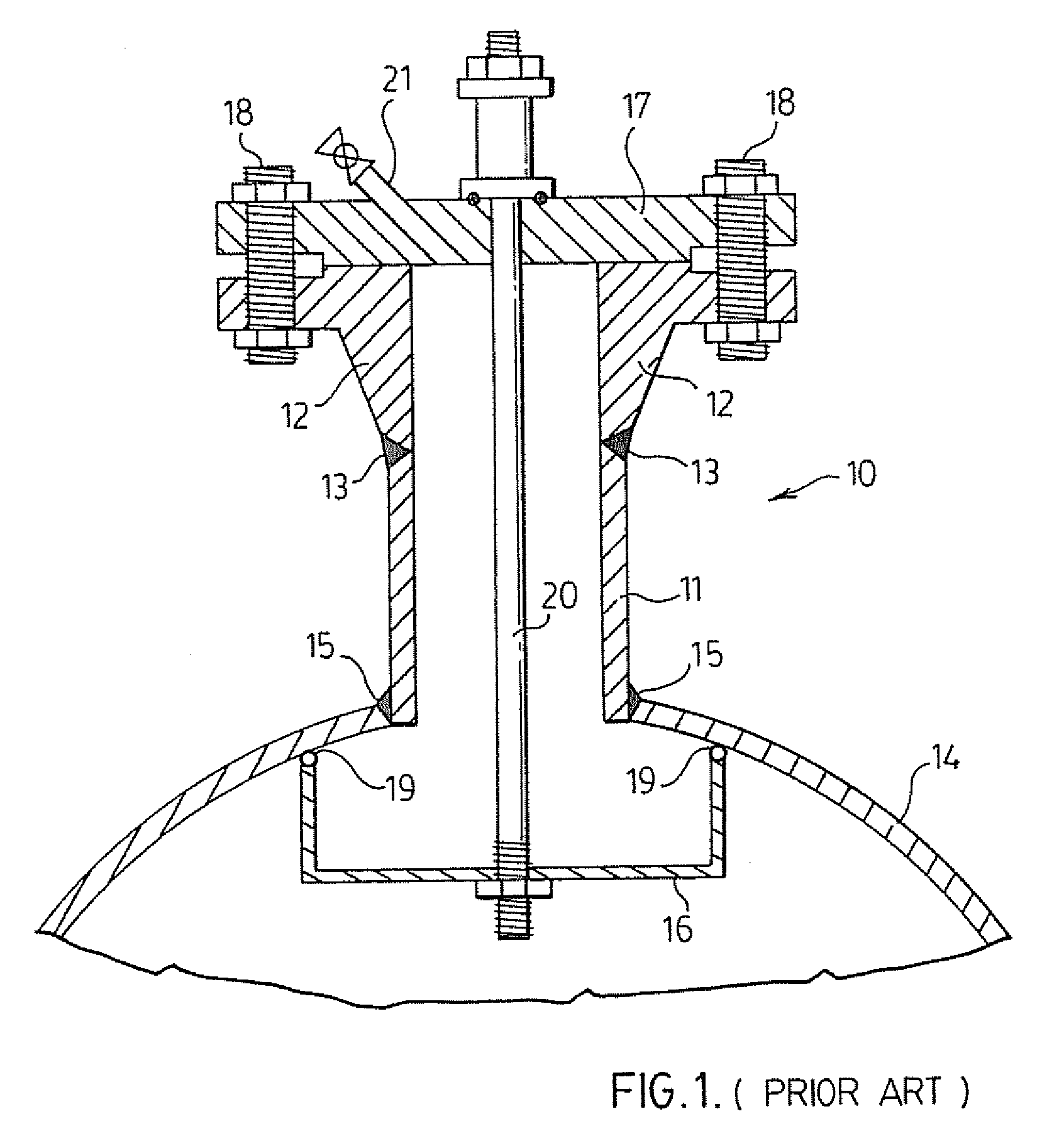
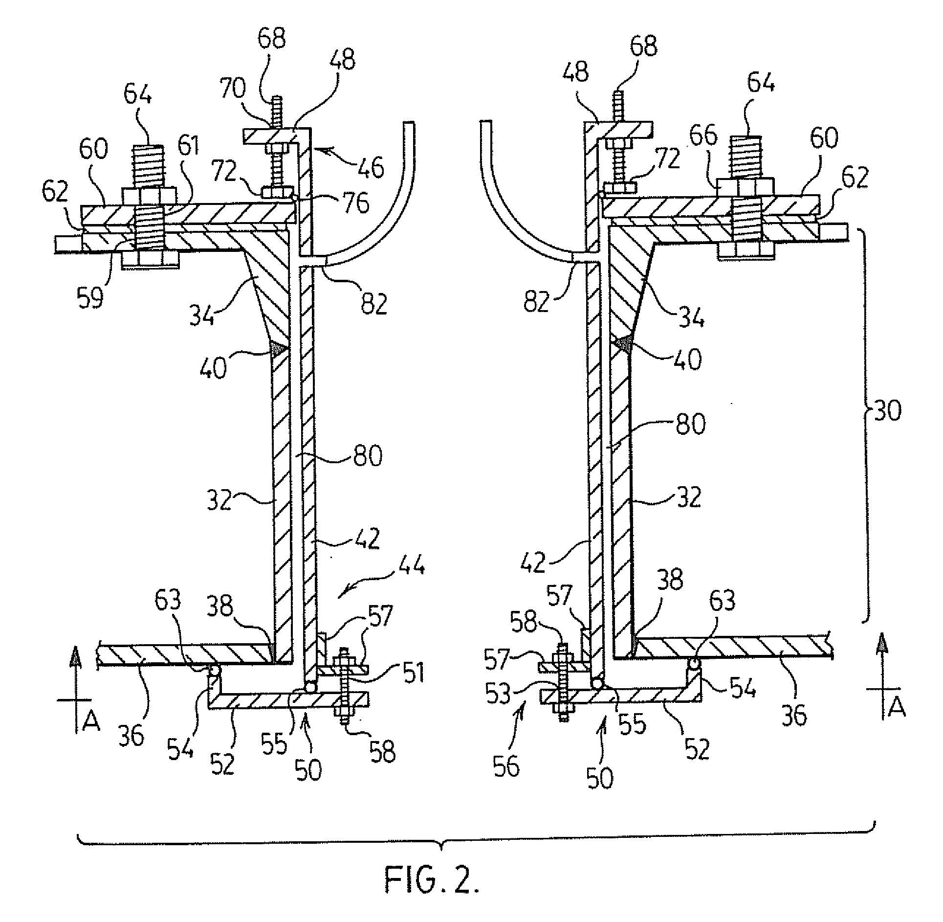
[0055]FIG. 1 illustrates...


PUM

PropertyMeasurementUnit
lengthaaaaaaaaaa
pressureaaaaaaaaaa
outer diameteraaaaaaaaaa

Abstract

A weld testing assembly for testing the integrity of weld used to secure a nozzle to a vessel and the like comprises a pair of plates or discs positioned on either end of the nozzle and a generally coaxially extending annular body having a diameter smaller than the nozzle stem. The assembly creates a sealed area with a small volume whereby a weld test can be efficiently conducted.

Description

CROSS REFERENCE TO PRIOR APPLICATIONS [0001] This application is a Continuation of PCT Application No. PCT / CA2005 / 001982 filed on Dec. 30, 2005, which claims priority from U.S. Provisional application No. 60 / 640,093, filed Dec. 30, 2004 and U.S. Provisional application No. 60 / 663,871, filed Mar. 22, 2005. The disclosures of the aforementioned related applications are incorporated herein by reference in their entirety.BACKGROUND OF THE INVENTION [0002] 1. Field of the Invention [0003] The present invention relates to apparatus and methods for testing welds and, more particularly, for testing welds on nozzles or other such fixtures. [0004] 2. Description of the Prior Art [0005] In chemical or petrochemical plants etc., it is often necessary to convey fluidic materials from one location, or holding cell to another. The conveyance of such material normally includes equipment such as conduits or pipes, storage or reaction vessels etc., which are generally manufactured from metal. The joi...

Claims


Application Information

Patent Timeline
Patent Type & Authority Applications(United States)
IPC IPC(8): G21C13/00G01M99/00
CPCB23K31/12F16L23/003F16L23/026G01M3/022G01M3/2884G01N2203/0296G01N3/12G01N2203/0048G01N2203/0208G01N2203/0256G01N2203/027G01N3/00
Inventor CARSON, GLENNHODGINS, JAMES
Owner CB CANADA ACQUISITION INC
Why Eureka
Try Eureka